Installation Instructions
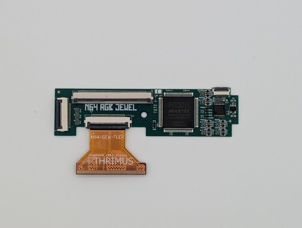
The N64 RGB JEWEL is an RGB mod that can be installed in either a standalone configuration, or as a dual upgrade with the PixelFX Retro GEM for dual simultaneous output of RGB and HDMI. Select the appropriate installation instructions below from the dropdown menus below.
Retro GEM Piggyback Install Instructions
These installation instructions assume that a Retro GEM is already fully installed and functional. If you are installing both mods at the same time you should follow PixelFX’s instructions to install and test the Retro GEM first before you follow this guide to install the N64RGB JEWEL.
Step 1:
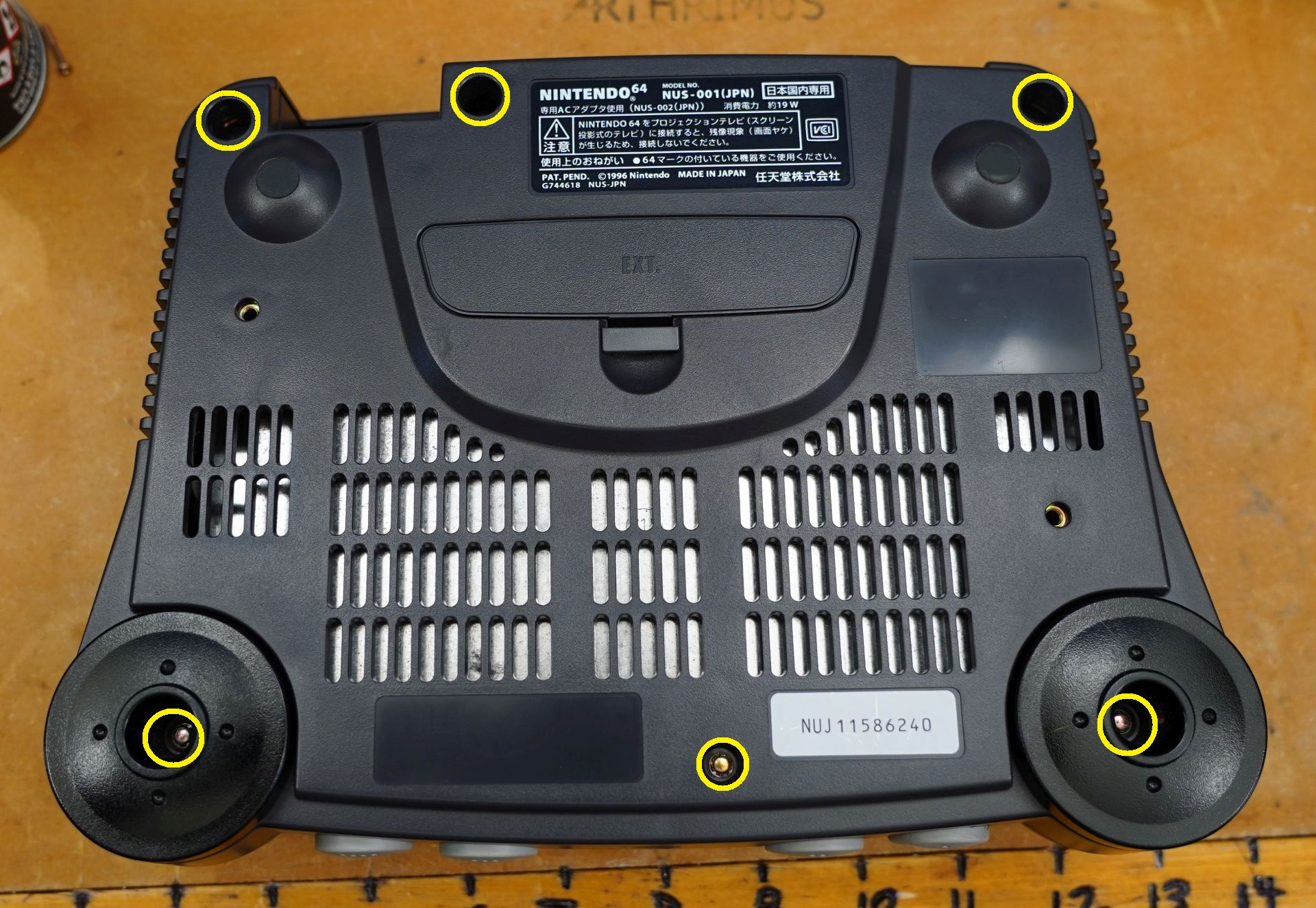
Remove all 6 screws from the bottom of the N64 shell. You will need a 4.5mm gamebit screwdriver.
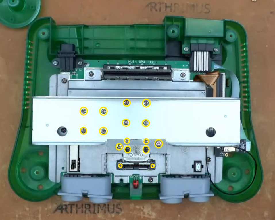
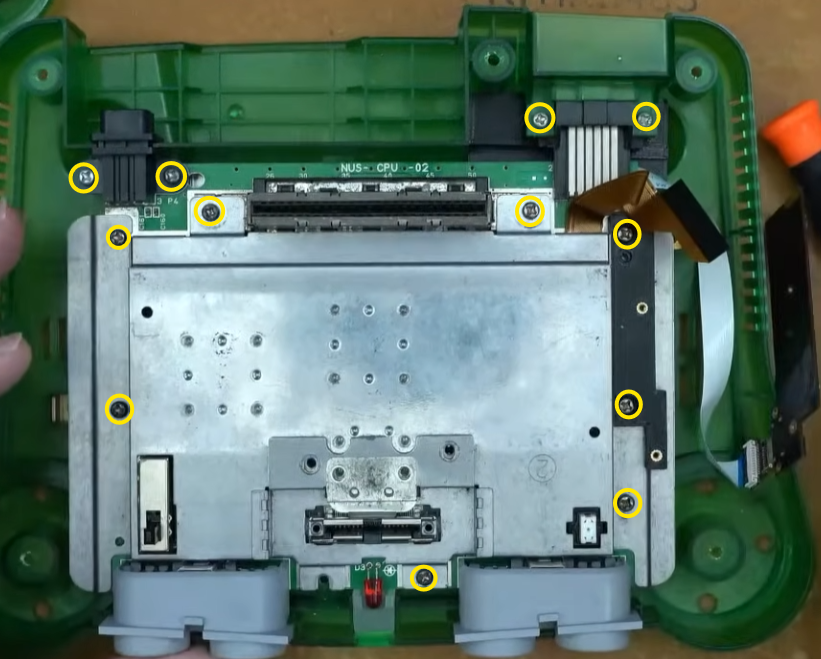
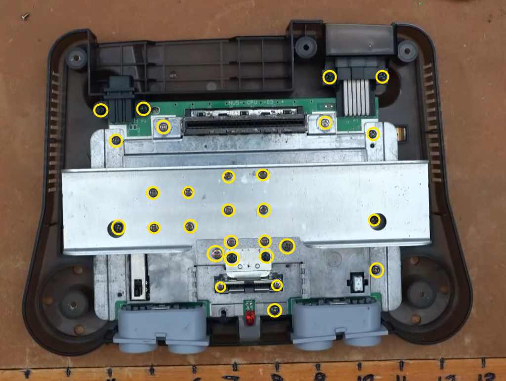
Then remove all of the screws on the shielding marked below.
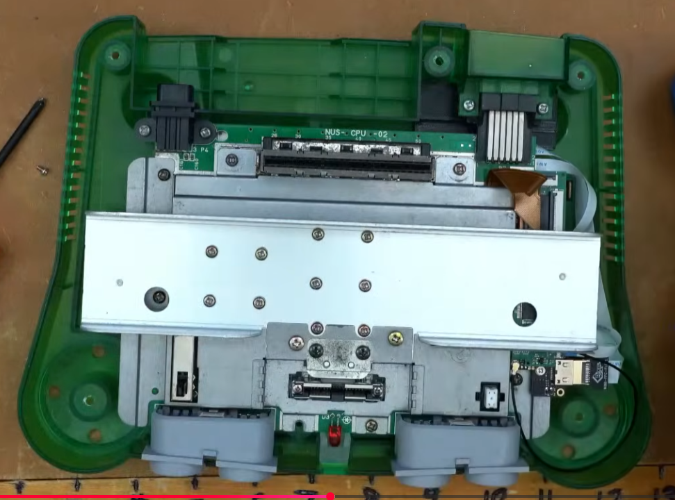
Remove the heatsink.
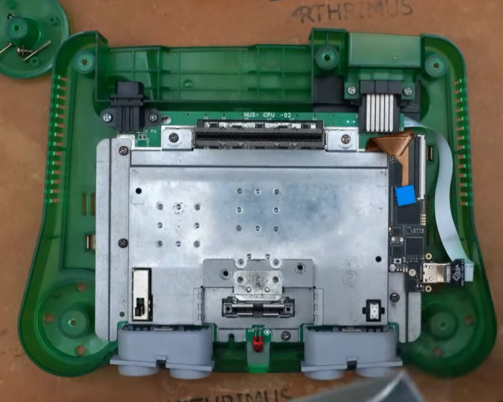
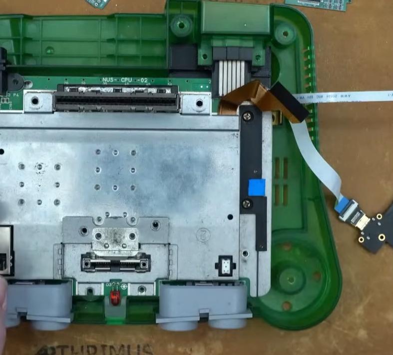
Remove the Retro GEM flex cable and remove the two screws holding the Retro GEM in place.
Step 2:
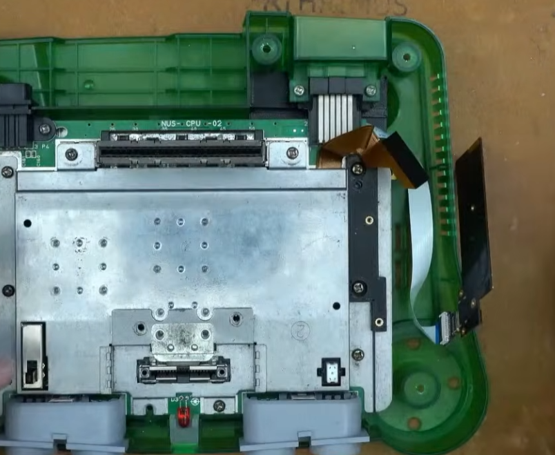
Remove the existing 3D printed mount and the remaining screws holding down the RF shield.
Remove the N64 motherboard from the shell and flip it over to the bottom side.
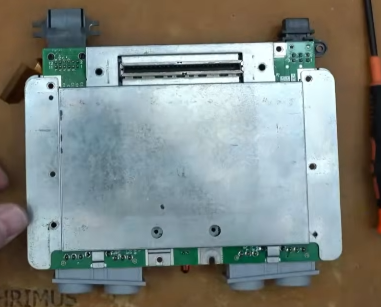
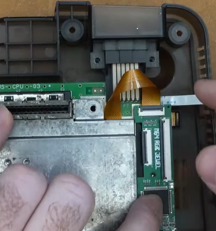
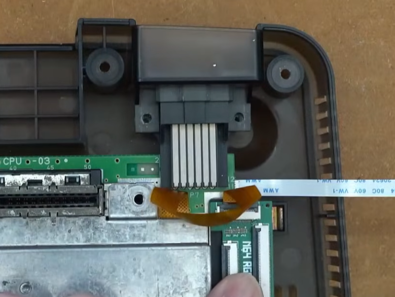
Place the N64 AV Breakout PCB over the pins of the AV Multi Out Connector.
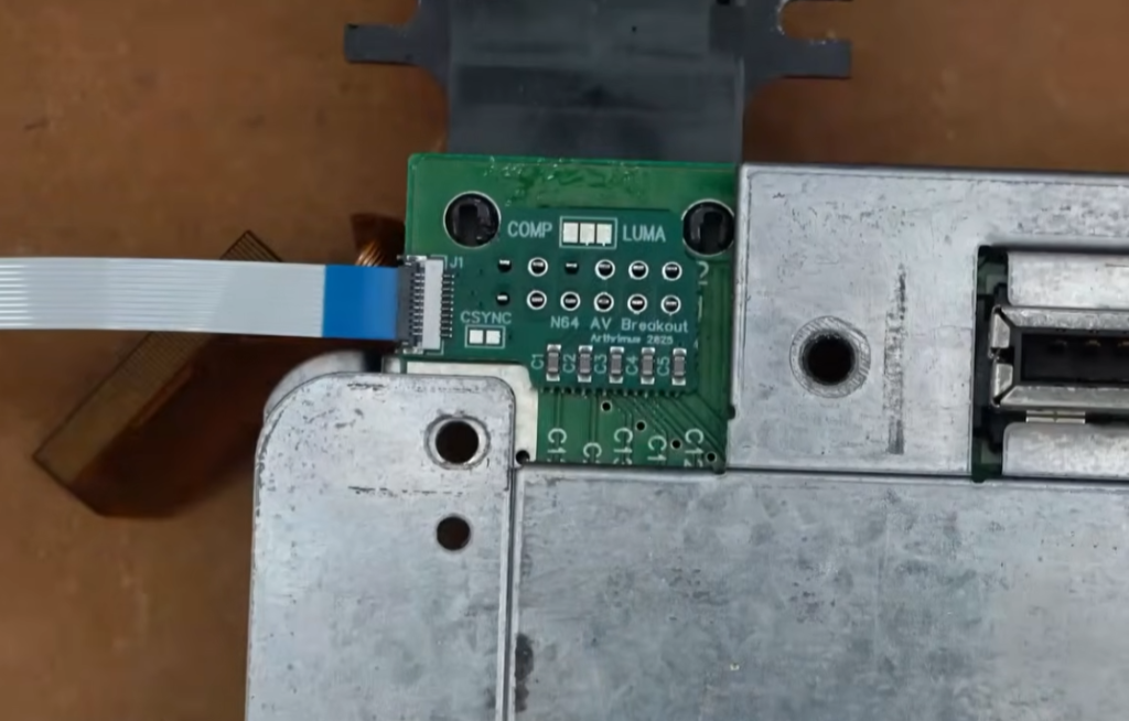
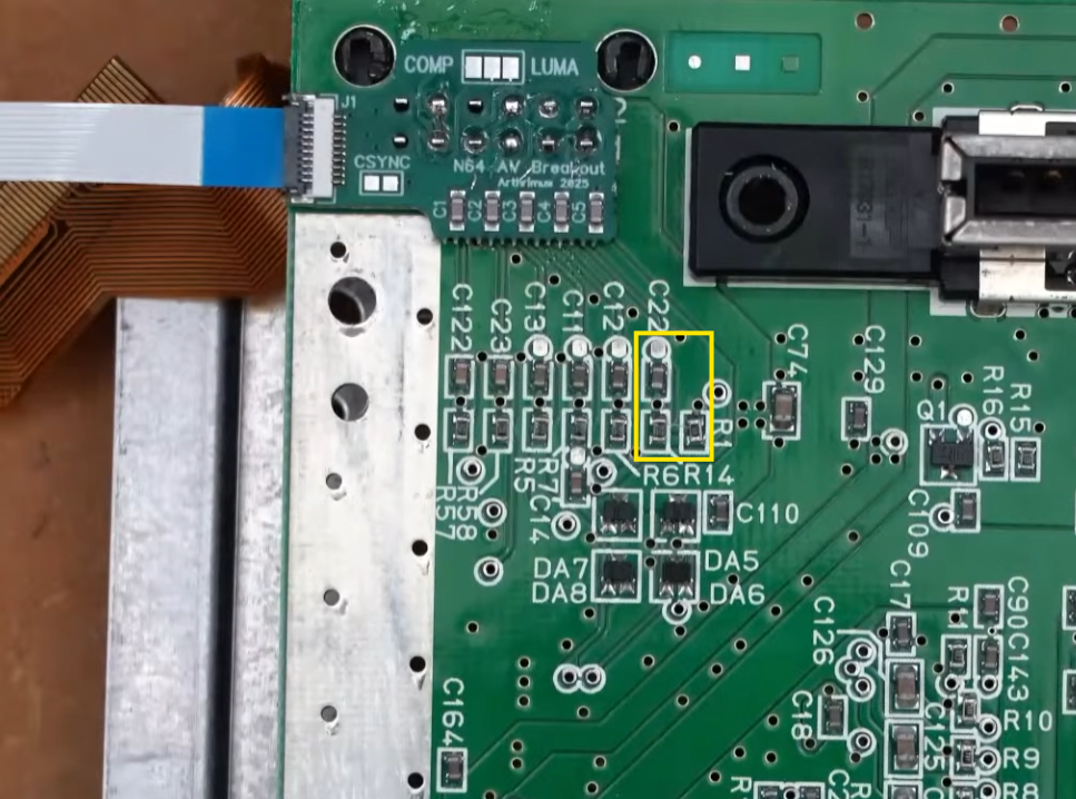
Remove the bottom RF shield to check if your motherboard has R1, R14, and C22 populated. If these components are populated then you can leave the CSYNC jumper on the N64 AV Breakout board open, if these components are not populated then you should solder the CSYNC jumper closed.
Once you are finished you can reinstall the rear RF shield and flip the N64 motherboard back over.
Step 3:
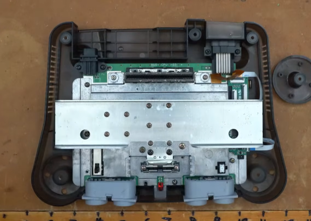
Reinstall the motherboard into the case and reinstall the top RF shield. Then install the new N64 Jewel 3D printed mounting bracket. Install the Retro GEM thermal pad into the cutout in the side of the mounting bracket.
Reinstall the Retro GEM on the new mounting bracket using only the bottom screw, leaving the top screw uninstalled.
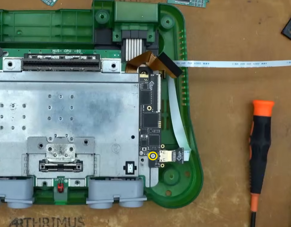
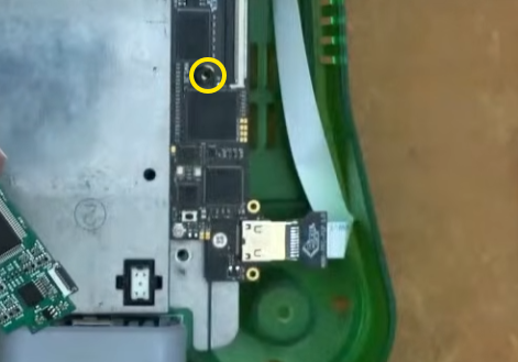
Place the included spacer over the top screw hole of the Retro GEM.
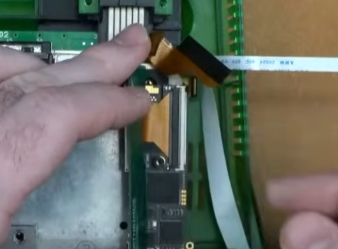
Install the N64-GEM-FLEX on the N64 RGB JEWEL PCB.
Insert the N64-GEM-FLEX into the Retro GEM’s FFC connector with pins on the flex cable facing down.
Fold the N64 JEWEL over and lay it down on top of the Retro GEM, aligning the screw hole with the spacer that you placed on the GEM PCB.
Install the included long M2 screw into the screw hole on the JEWEL, making sure to align the spacer and the screw hole on the Retro GEM.
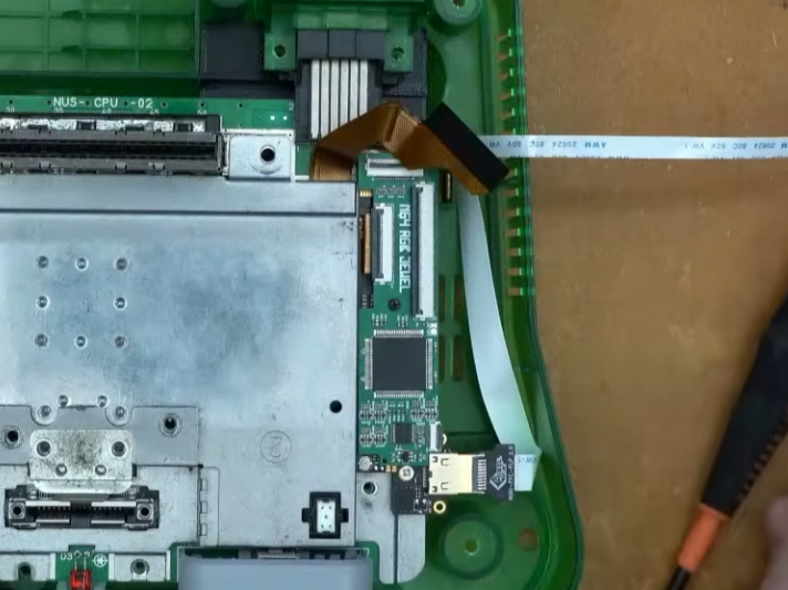
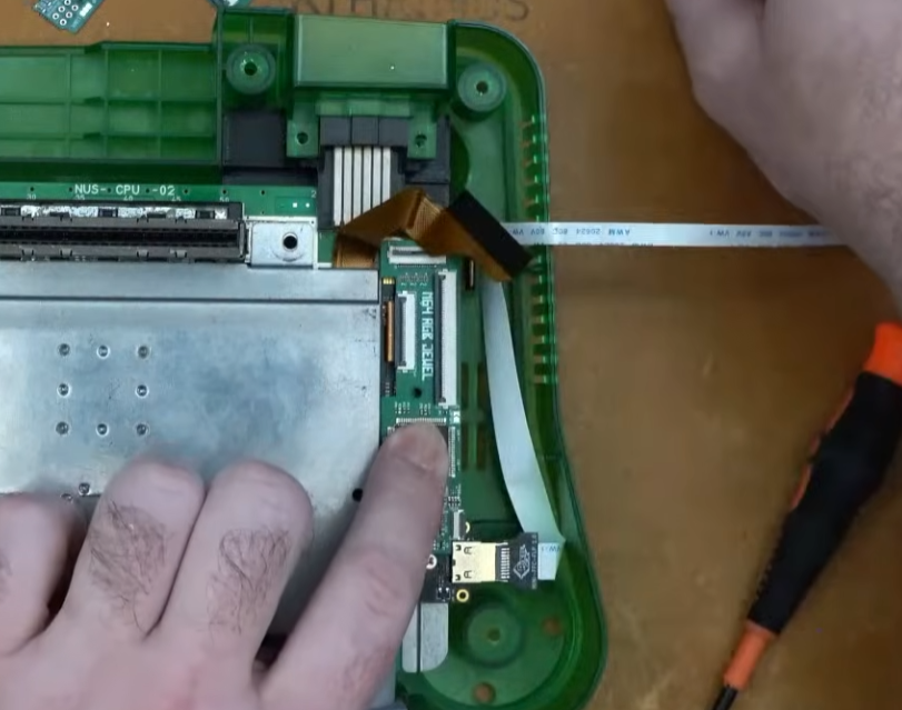
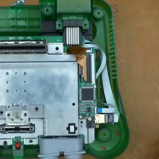
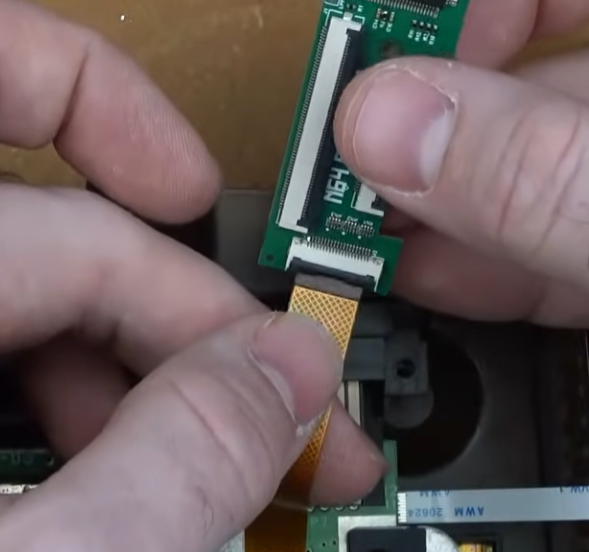
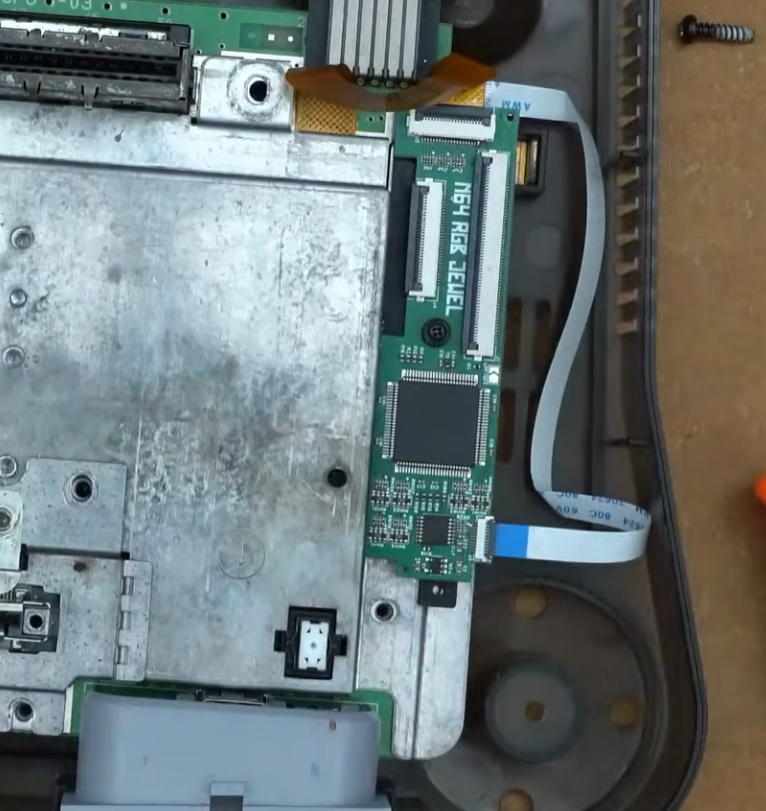
Insert the Retro GEM flex cable into the N64 RGB JEWEL FFC connector.
Insert the N64 AV Breakout Board Flex cable into the FFC connector on the N64 RGB JEWEL PCB.
Step 4:
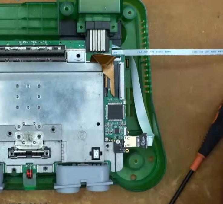
Reinstall all the heatsink and all of the screws.
Reassemble the shell and test the RGB output. If everything works then you’re done!
Standalone Install Instructions
These installation instructions assume that your N64 has no existing RGB or HDMI output upgrades installed.
Step 1:
Remove all 6 screws from the bottom of the N64 shell. You will need a 4.5mm gamebit screwdriver.
Then remove all of the screws on the shielding marked below.
Step 2:
Remove the N64 motherboard from the shell and remove the heatsink and RF shield.
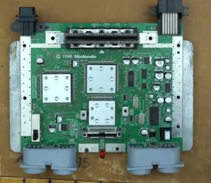
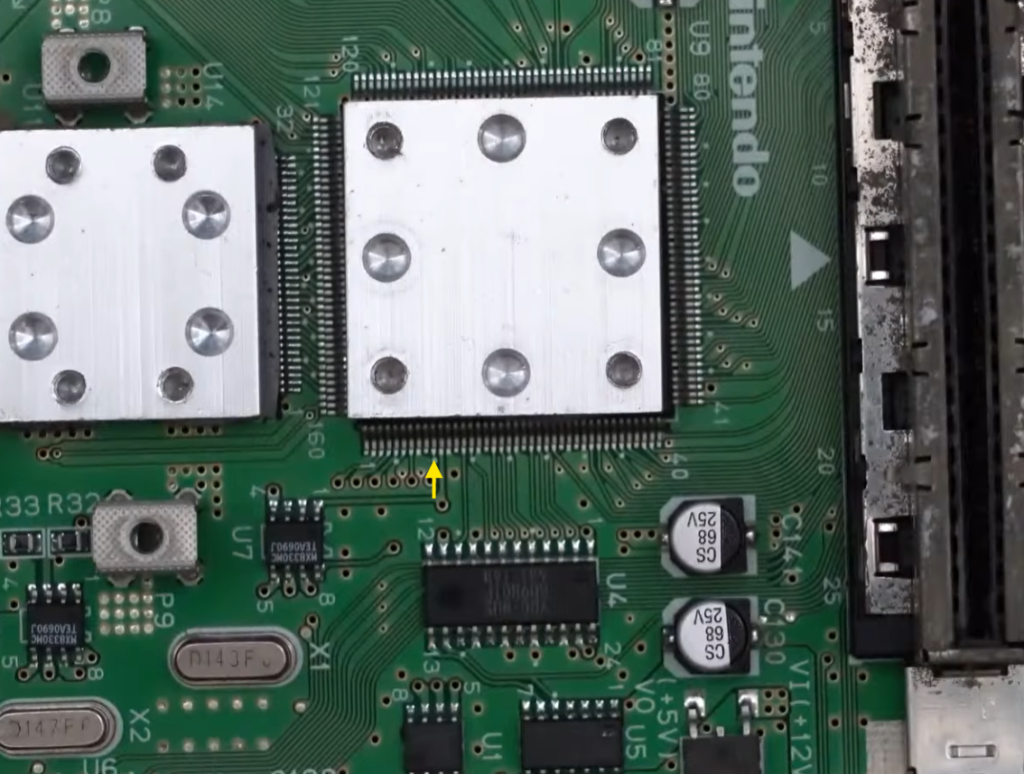
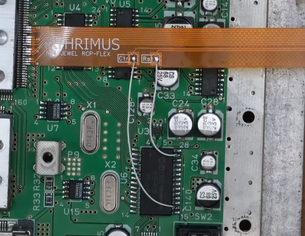
Align the edge of the N64 JEWEL RCP FLEX with pin 10 of the RCP chip on the N64 Motherboard.
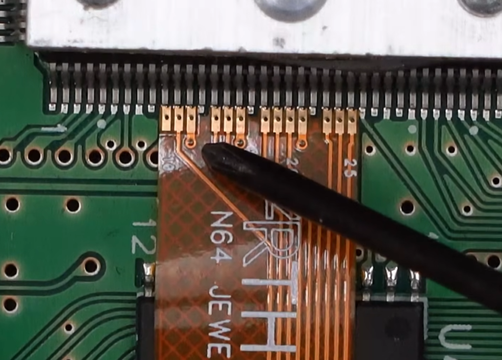
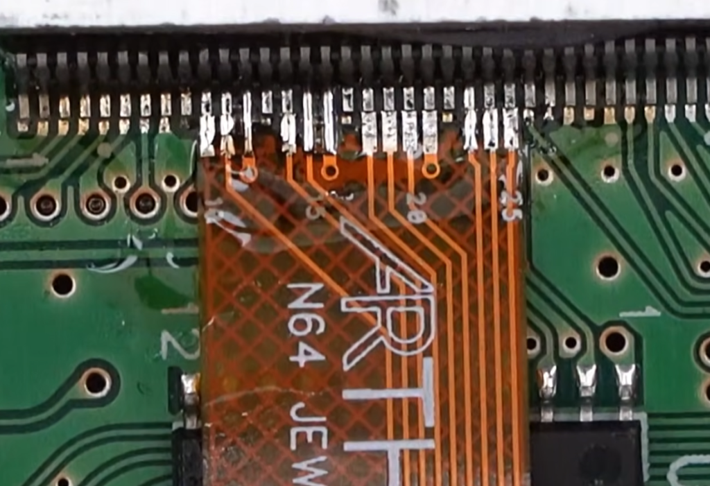
Solder the RCP flex in place.
Install two wires on the PIF NUS chip. One on pin 16 and one on pin 27.
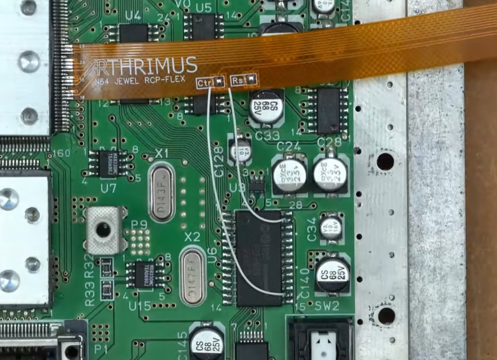
Solder the wire from pin 16 to the Ctrl pad on the RCP-FLEX and solder the wire from pin 27 to the Rst pad on the RCP-FLEX.
Step 3:
Apply Kapton tape to the top of the Ctrl and Rst pads to prevent shorts, then fold the RCP-FLEX upwards.
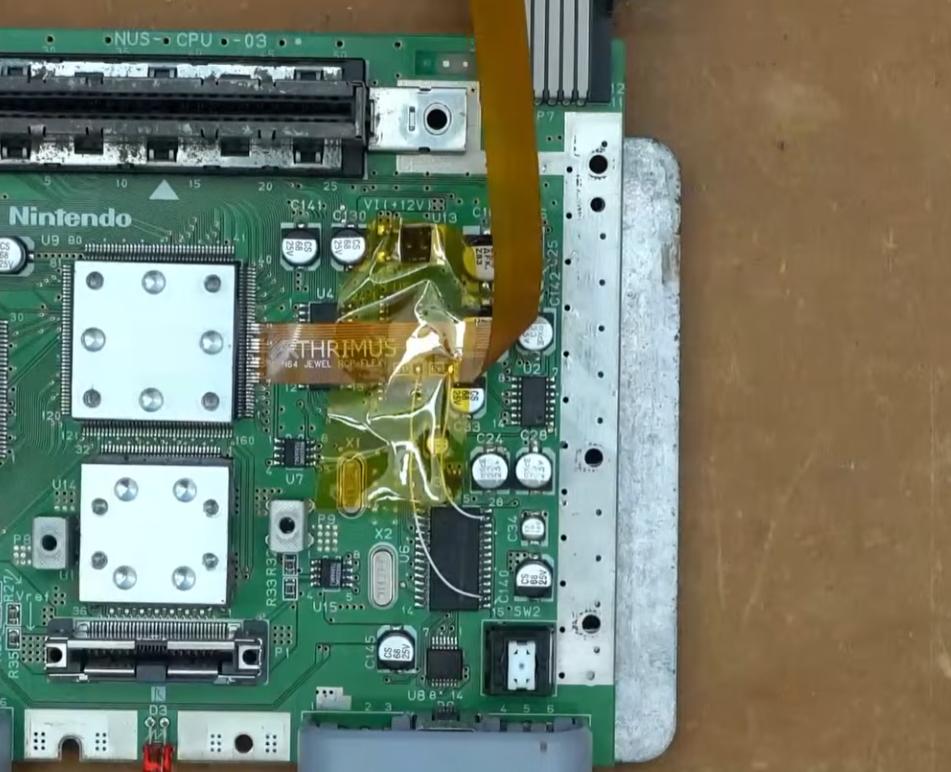
Reinstall the RF shield making sure that the RCP-FLEX is not pinched by the shield.
Step 4:
Flip the N64 Motherboard over to the bottom side.
Place the N64 AV Breakout PCB over the pins of the AV Multi Out Connector.
Remove the bottom RF shield to check if your motherboard has R1, R14, and C22 populated. If these components are populated then you can leave the CSYNC jumper on the N64 AV Breakout board open, if these components are not populated then you should solder the CSYNC jumper closed.
Once you are finished you can reinstall the rear RF shield and flip the N64 motherboard back over.
Step 5:
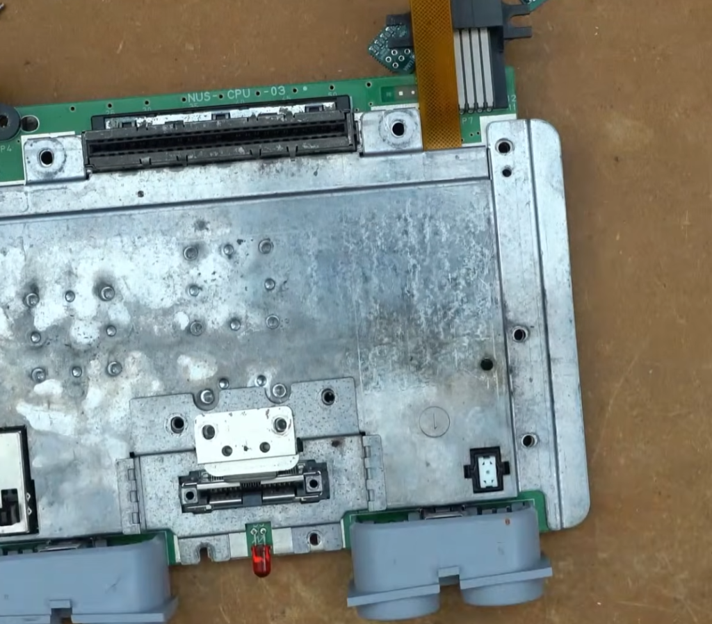
Reinstall the motherboard into the case and reinstall the top RF shield. Then install the new N64 Jewel 3D printed mounting bracket.
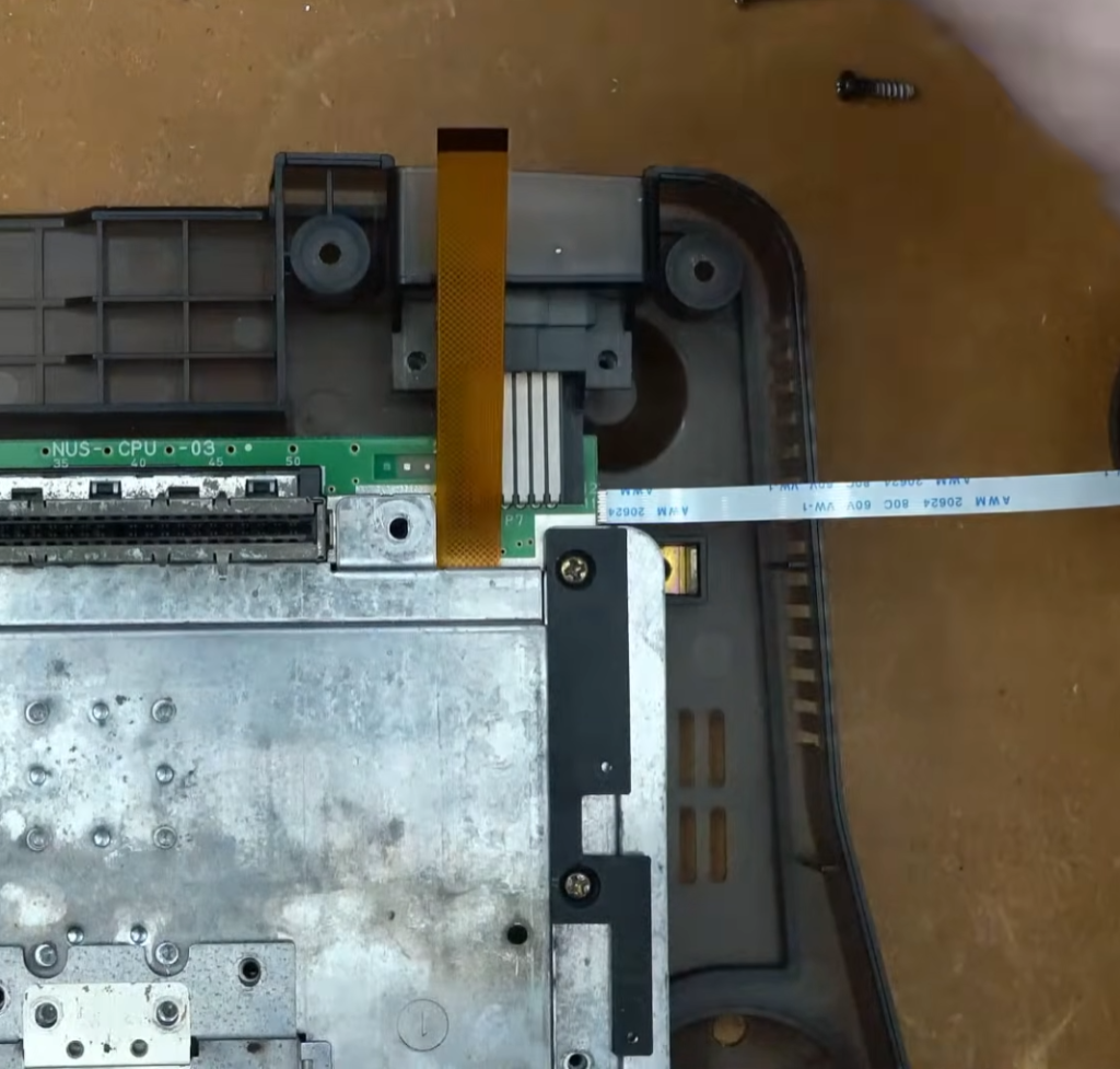
Insert the RCP-FLEX into the FFC connector on the N64 RGB JEWEL PCB.
Flip the N64 RGB JEWEL over and align it on the mounting bracket.
Gently fold the RCP-FLEX down.
Install the included M2 screw with the included spacer installed between the screw and the N64 JEWEL PCB.
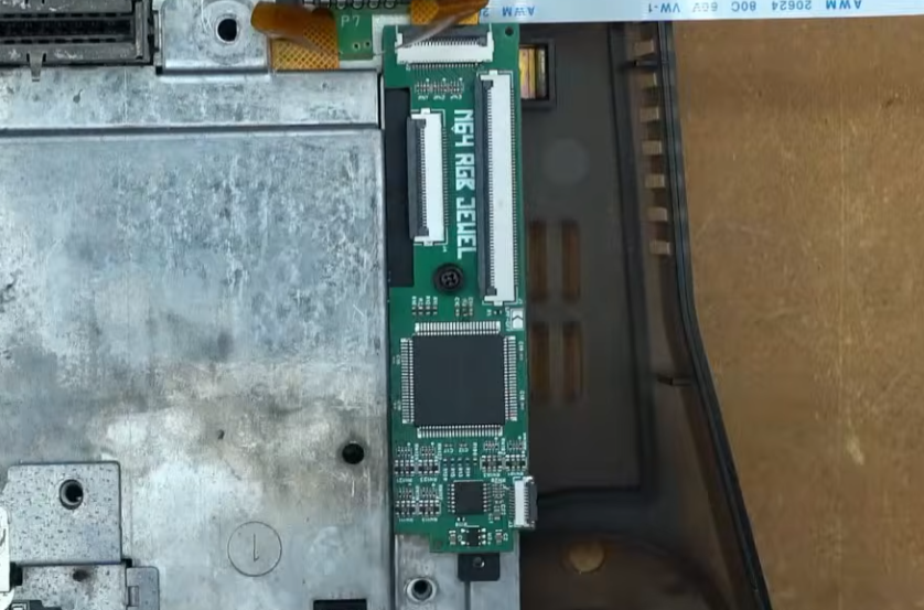
Insert the N64 AV Breakout flex cable into the FFC connector on the N64 RGB JEWEL PCB.
Reinstall the heatsink and all internal screws.
Reassemble the shell and test the RGB output. If everything works then you’re done!