Product Overview
The Console JAMMAizer is a device that is designed to convert home video game console controls, video output, and audio output into a format compatible with arcade cabinets that follow the JAMMA wiring standard. This task requires amplification of both the RGB video signal, and the line level audio signal from a home console and a method of connecting controls from the console to the JAMMA edge connector.
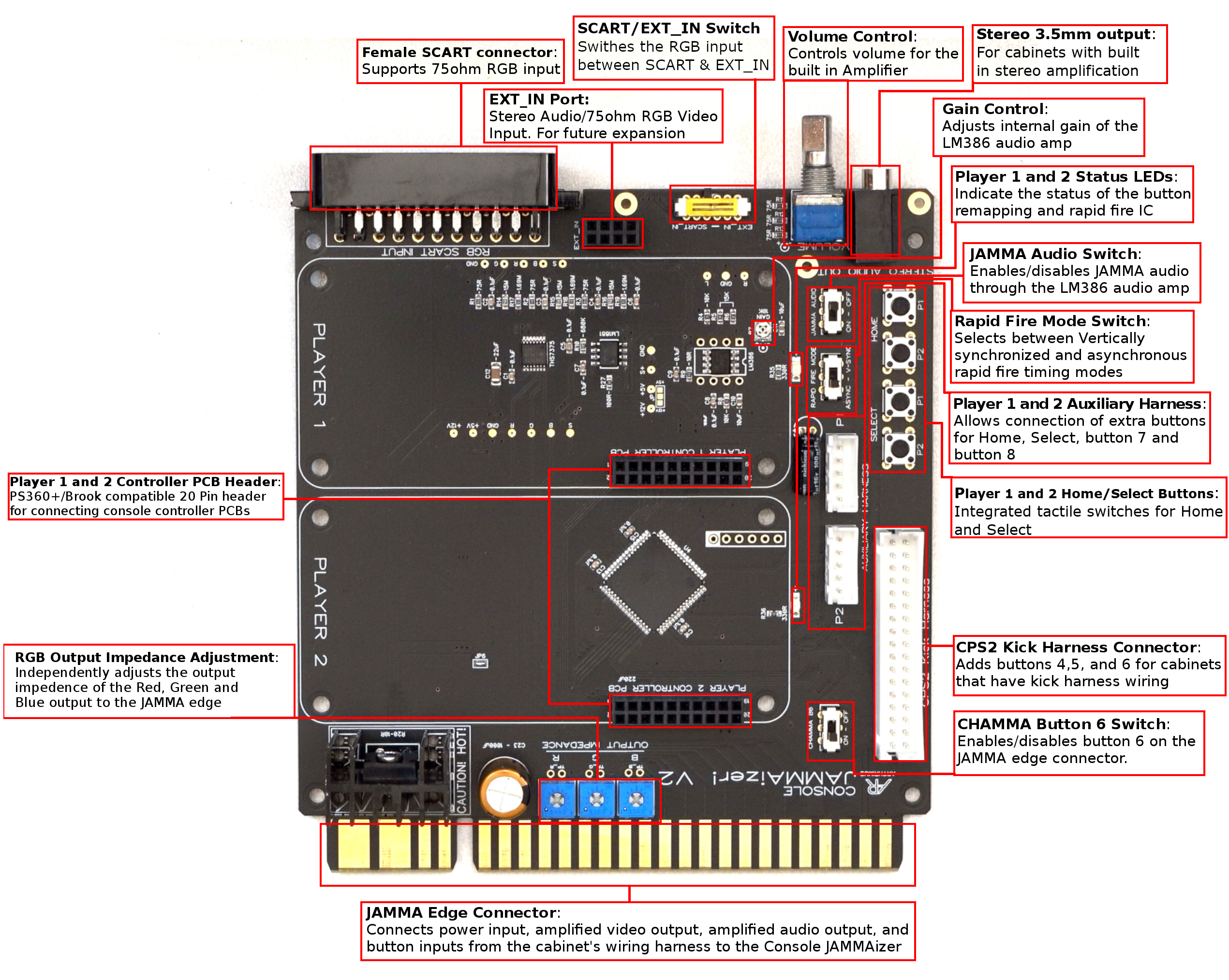
The following image is a visual representation of the major components of the Console JAMMAizer.
Scart Input
The Console JAMMAizer natively supports 75ohm RGBS video, and line level audio through it’s Scart input. Video and audio signals are amplified using a THS7375 and LM386 respectively so they can conform to the JAMMA video and audio standards. The Console JAMMAizer’s Scart socket can accept 15khz and 31khz RGB input, but keep in mind that it does not perform any scan rate conversion. Therefore you must make sure that the arcade monitor supports the scan rate of your input signal.
EXT_IN
The Console JAMMAizer supports additional inputs through the EXT_IN header. This header is meant for connecting expansion audio/video input boards for non Scart inputs. Currently the only existing input expansion device is the VGA hat, but there is the possibility of other formats such as Component, S-Video or Composite inputs as well.
SCART/EXT_IN Switch
This switch controls whether the SCART port or the EXT_IN port is the active input.
Stereo 3.5mm Out
Some cabinets may have external stereo amplification outside of the JAMMA mono audio standard. For these cabinets the stereo audio output allows you to run line level audio to your cabinet’s stereo amplifier.
Volume Control
Much like an arcade PCB the Console JAMMAizer’s volume can be controlled using the volume control potentiometer. Volume control only affects JAMMA mono audio output.
Gain Control
The LM386 has internal gain control that can be adjusted using the SMD trimmer potentiometer on the Console JAMMAizer PCB. This should usually be set as low as possible unless you have an exceptionally quiet audio source.
Player 1 and 2 Status LEDs
These status LEDs are used by the button remapping and rapid fire IC to indicate when you are in the programming modes for these features. Further details will be in the section on the button remapping IC
JAMMA Audio Switch
When using RCA output you can turn off JAMMA audio using this switch.
Rapid Fire Mode Switch
The rapid fire function can operate in two modes. V-Sync or Async. In V-Sync mode the rapid fire is synchronized to the vertical sync of the console. In Async mode the rapid fire is not synchronized to the vertical sync of the console.
Auxiliary Harness
The auxiliary harness connector allows you to add extra wiring for Button 7, 8, Select, and Home. This is convenient for users that have 8 button control panels, and/or additional button panels. The pinout for the auxiliary harness is as follows.
- Select
- Home
- B7
- B8
- GND
Each player has it’s own harness connector. Connector type is JST NH.
Home and Select Buttons
In case you do not have auxiliary buttons for home and select, and you do not wish to use home/select emulation, there are tactile switches for home and select for player 1 and 2.
CPS2 Kick Harness Connector
For cabinets that do not support buttons 4,5 and 6 on the JAMMA edge they can be connected through the CPS2 Kick harness connector.
CHAMMA Button 6 Switch
Toggles button 6 to the JAMMA edge. Some cabinets may be wired for button 6 on the JAMMA edge. If so you can turn this switch on, and you will not need a kick harness. Otherwise keep this switch turned off.
JAMMA Edge
The JAMMA edge connector provides audio/video output to the cabinet, and control inputs to the PCB.
RGB Output Impedance Adjustment
Some monitors may require output impedance adjustment. If your image is too bright, or too dark, you will want to adjust these trimmer potentiometers until you reach the desired image. You can check the impedance measurement with a multimeter connected to the two vias labeled TP above each trimmer pot.
Controller PCB Header
This is where you connect the Player 1 and 2 controller PCBs. These headers are compatible with the PS360+ 20 pin header pinout. This makes PS360+ and all of Brook’s Fighting Board PCBs drop in compatible with the Console JAMMAizer. This header is also compatible with my MC Cthulhu EZ PCB.
Usage Instructions
This section covers how to use the features of the Console JAMMAizer.
Hooking Things Up
With your arcade cabinet powered off connect your Console JAMMAizer to your arcade cabinet’s JAMMA harness, kick harness (if applicable), and stereo input (if applicable).
Connect your console’s video and audio using a SCART cable, or using a VGA cable and 3.5mm TRS jack if using the VGA hat.
Connect your controller PCB/s 20 pin male header to the Player 1 and 2 controller PCB female header on the Console JAMMAizer. Optionally secure your controller PCB/s to the four standoffs using the included M3 screws.
Connect your controller PCB/s to your console’s controller port/s using the appropriate cable/s.
Power your arcade cabinet on first, then power on your console. Upon startup, if you have a button remapping IC installed in your Console JAMMAizer the player 1 and 2 status LEDs should flash repeatedly for a second.
Once everything is powered on you are good to go. Always remember to power on your arcade cabinet before powering on your console. If you do this in the wrong order your controller PCB/s may not be properly recognized.
Button Remapping and Rapid Fire Programming
The Console JAMMAizer’s Button Remapping and Rapid Fire modes work as follows.
Button Remapping mode
1. Press and hold down two arbitrary buttons and the START button for 3 or more seconds. After 3 seconds an appropriate status LED on the board will light up and buttons will no longer register – this means the remapping chip has entered the button remapping mode and you can release the buttons.
2. Right after you release the last of the buttons held down, you can set a new button layout by pressing buttons.
3. Each press of a button corresponds to the JAMMA button number. If you press a button once, it will be JAMMA button 1, twice – button 2, thrice – button 3, it works up to button 8. The ninth press disables the button; the 10th press starts the countdown over. No button press means the button will not be set.
Additionally, each press of a button is indicated be the status LED blink.
4. To exit the button configuration mode and save your new layout, press the START button.
Side note: Every time you access this mode, your previous layout will be erased and you will need to set your layout anew. This is an easy and fast way to reset your settings.
Autofire mode
- Press and hold down one arbitrary button and the START button for 3 or more seconds. After 3 seconds an appropriate status LED on the board will light up and buttons will no longer register – this means it has entered the autofire mode and you can release the buttons.
- Right after you release the last of the buttons held down, you can enable the autofire feature by pressing buttons.
- Each press of a button corresponds to the autofire rate.
One press -> 1/2 of the game’s VSYNC speed,
Two presses -> 1/3 of the game’s VSYNC speed,
Three presses -> 1/4 of the game’s VSYNC speed,
Four presses -> 1/6 of the game’s VSYNC speed,
Five presses -> 1/8 of the game’s VSYNC speed,
Six presses -> 1/10 of the game’s VSYNC speed,
The seventh press disables autofire; the eighth press starts the countdown over. No button press means the autofire will not be set.
Additionally, each press of a button is indicated be the status LED blink.
- To exit the autofire mode and save the settings, press the START button.
Side note: Just like in the button remapping mode, your previous autofire settings are being erased the moment you access the autofire mode. Consequently, if you want to reset all autofire settings, just enter the autofire mode and exit it without pressing any button.
Instructions on profile selection:
The Console JAMMAizer supports 6 independent Button Remapping and Auto Fire profiles per player. In order to select a profile you must hold one of the following button combinations for 3 seconds.
Profile #1 = Start + B1 + B2 + B3
Profile #2 = Start + B2 + B3 + B4
Profile #3 = Start + B3 + B4 + B5
Profile #4 = Start + B4 + B5 + B6
Profile #5 = Start + B5 + B6 + B1
Profile #6 = Start + B6 + B1 + B2
Home and Select Emulation
For those who do not want to install additional buttons for Home and Select there is built in Home and Select emulation via button combination. The combinations for home and select are as follows:
Select = B1+B2+Start
Home = B2+B3+Start
When the select or home combo is detected, the start button press will not be sent. This is to avoid conflicts between the start and select buttons.
If desired, home and select emulation can be disabled or enabled by holding down either Player 1 or Player 2 START while powering up your cabinet:
VGA Hat
The VGA Hat accessory is a convenient way to connect PCs for MAME, as well as Deamcast and Xbox 360. The VGA hat simply passes the RGB signal from the VGA source to the EXT_IN header of the Console JAMMAizer. It also contains a Sync Combiner circuit that can combine H/V sync into C-sync for 31khz sources.
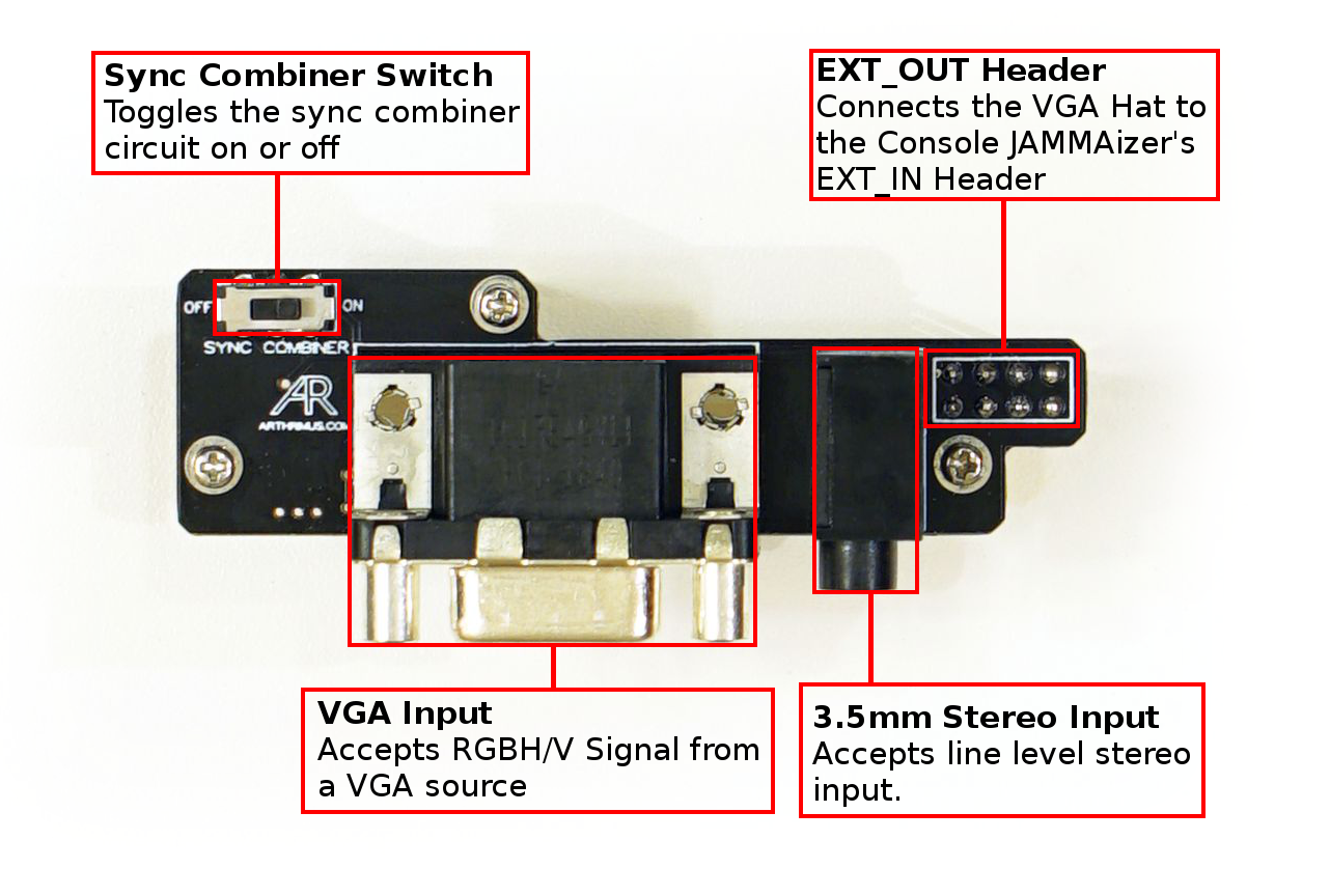
Note: The VGA hat does not perform any scan rate conversion. If you connect a 31khz source make sure you have a 31khz capable monitor. If you are using this for MAME with a 15khz monitor, you still need to use something like CRTEMU drivers to force 15khz output from your graphics card.
Adjusting Output Impedance
Due to variations in the behavior of some arcade monitors the option to adjust the output impedance of the RGB signal has been provided in the form of individual potentiometers for R, G, and B. Turning the potentiometers clockwise decreases output impedance, turning the potentiometers counter clockwise increases impedance.
If your image is too bright or colors are blown out, you need to increase your output impedance. If your image is too dark and colors are muted you need to decrease your output impedance.
You can check the output impedance setting using the vias labled TP_R, TP_G, and TP_B for R, G, and B respectively. In stock form they are adjusted to approximately 475ohms but you can adjust them anywhere from 1Kohm all the way down to 0ohms. For most monitors the stock settings will look great and likely won’t need any adjustment.