iFlash2PS2, a solution for using SD cards as HDD devices on PS2 Slim. Here you will find support the iFlash2PS2 such as compatibility information and the installation process.
Compatibility:
The iFlash2PS2 is currently known to be compatible with all GH-035-XX and GH-032-XX motherboards. This covers all SCPH-700XX model numbers.
Install Demonstration Video:
Install Process:
The following will cover the installation process for the iFlash2PS2 Kit. The workflow of the installation goes as follows.
- PS2 Disassembly
- Main Flex Cable Install
- Power Board Install
- SD Card Extender Flex Install
- 3D Printed Frame Install
- iFlash Solo Prep
- iFlash Solo Install
- Reassembly
PS2 Disassembly:
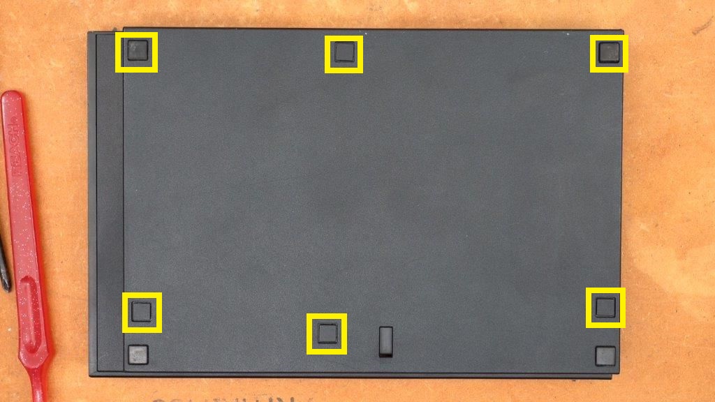
Step 1:
Flip your console over and remove the marked screw covers from the bottom of your PS2
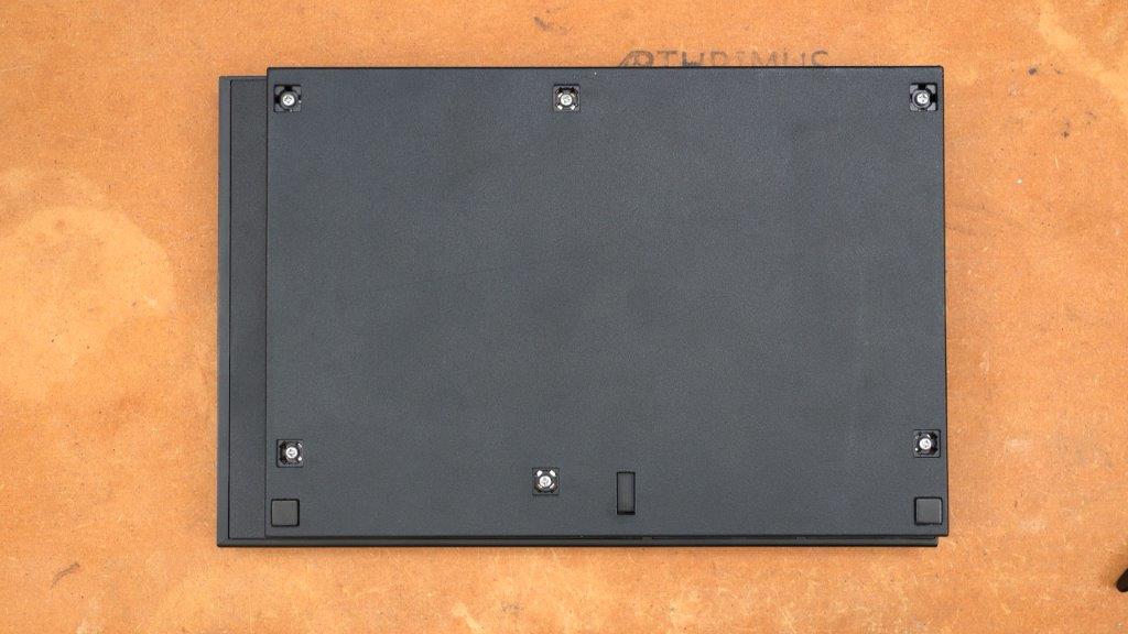
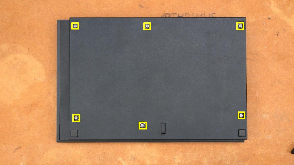
Step 2:
Remove the 6 screws on the bottom of the console.

Step 3:
Flip your console back over and remove the top shell as shown below.
Step 4:
Remove the modem by removing the 2 screws marked below. (Note, if you are installing this in an SCPH-70001 console you can skip the modem steps because those models do not have the modem installed.)
Step 5:
Remove disc drive sled screws marked below.
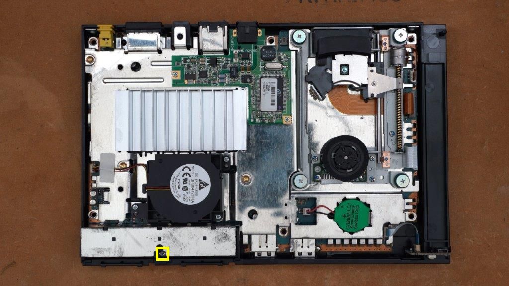
Step 6:
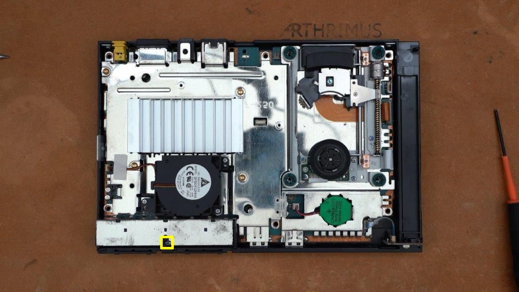
Carefully slide the disc sled out of the way and remove the screw marked below.
Step 7:
Remove controller port screw marked below.
Step 8:
Remove the motherboard from the bottom shell by tilting it upward from the rear of the console. Also carefully remove the Power/Reset switch board.
Step 9:
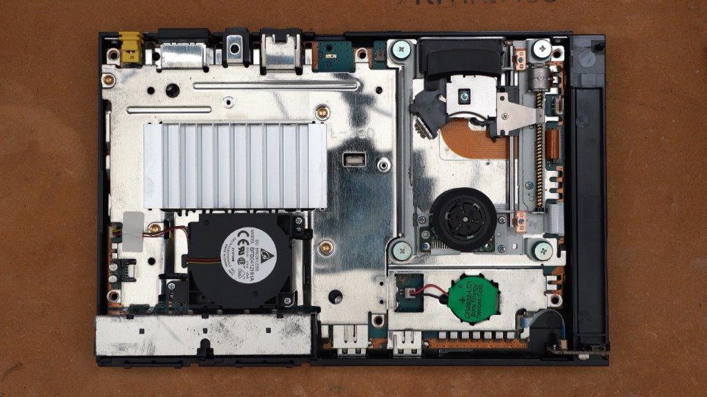
Flip the motherboard while holding the drive sled in place so it does not fall or get damaged.
Step 10:
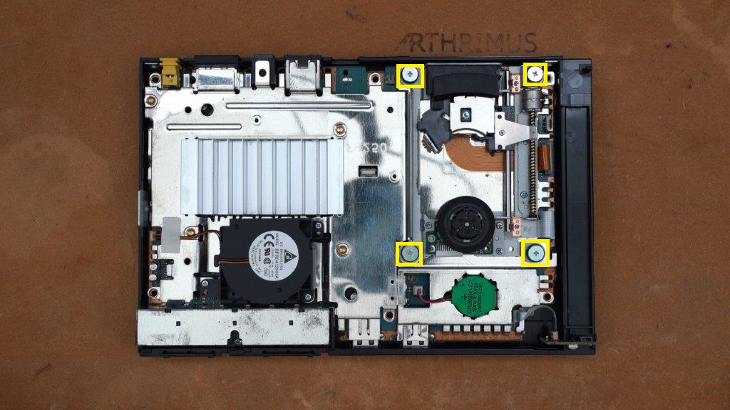
Remove heatsink screws marked below.
Step 11:
Remove rear shield.
Carefully flip the motherboard back over while holding the disc drive sled in place so it does not fall.
Step 12:
Disconnect battery, fan, and disc drive cables from the motherboard.
The white drive spindle motor cable simply pulls straight out. The laser flex cable has a locking connector so you must first lift up the lock on the connector, then you can lift the laser flex out of the connector, the drive sled motor flex simply pull straight out.
Step 13:
Remove top shielding. Be careful to slide the power reset flex cable out of the way of the shield as you are removing it so it is not damaged.
This concludes the disassembly step of the install process.
Main Flex Cable Install:
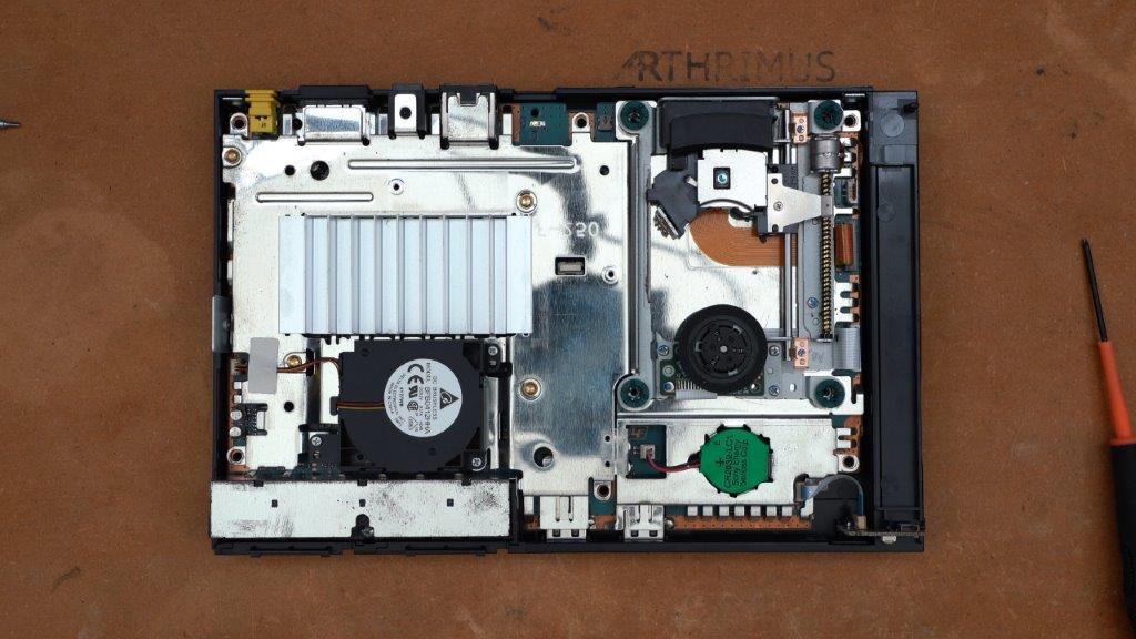
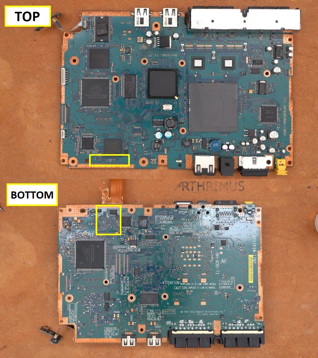
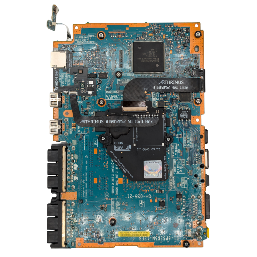
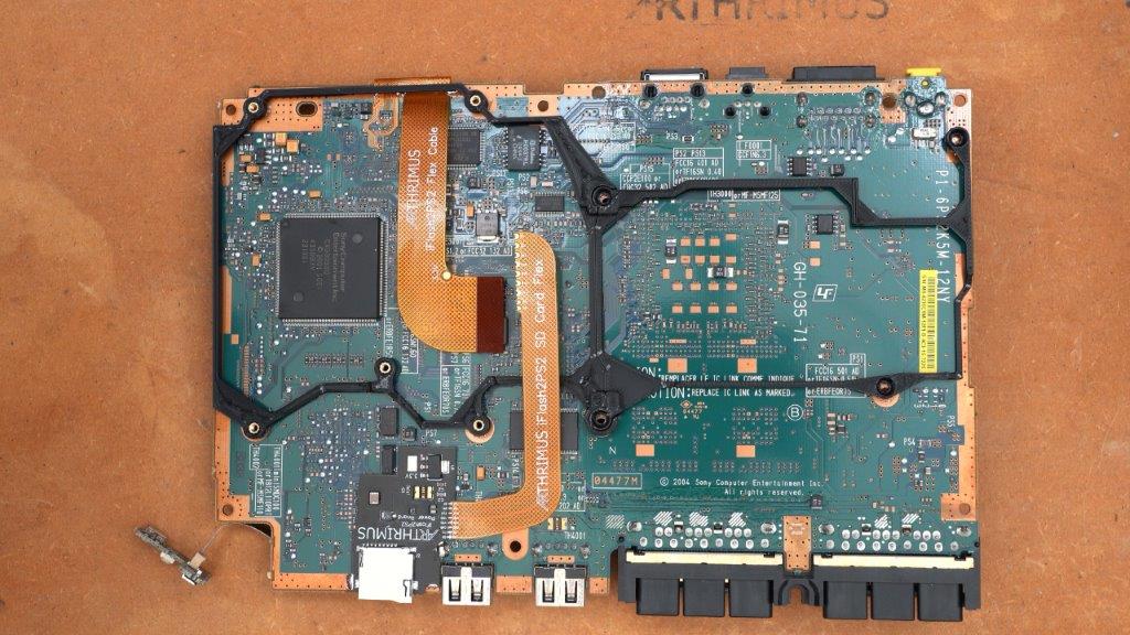
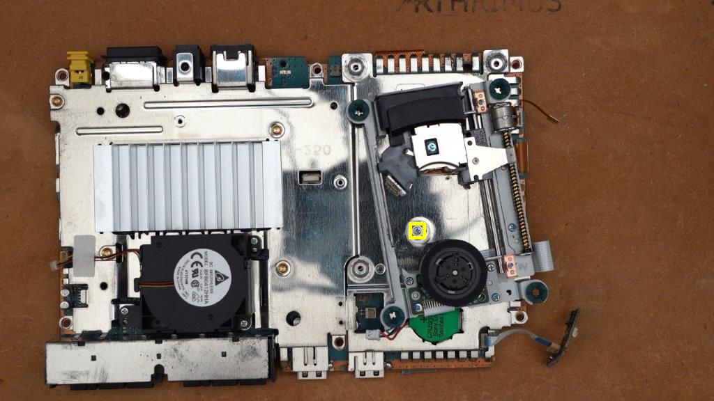
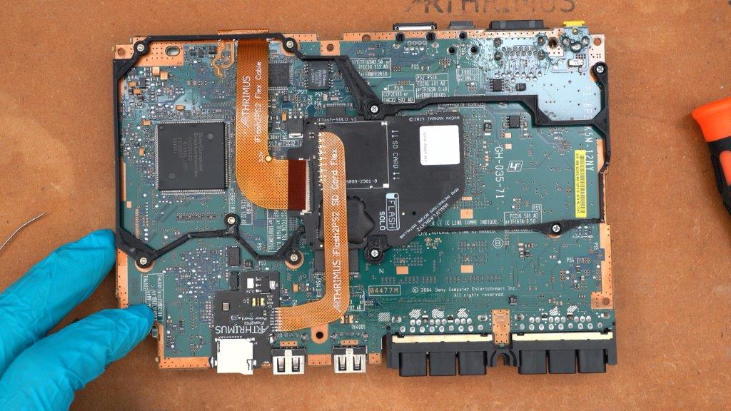
Motherboard working area overview. The areas that the main flex will be installed are marked below.
Step 1:
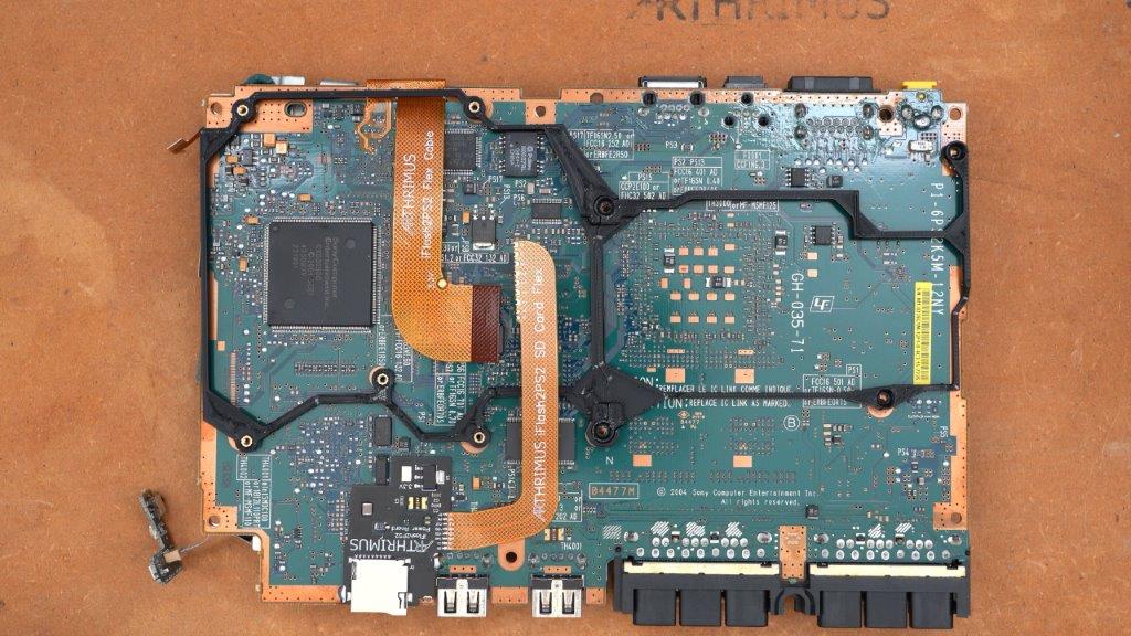
Position the iFlash2PS2 flex cable on the top side of the PS2 motherboard as shown below.
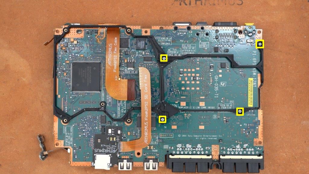
Solder the anchor points marked below to lock in the position of the flex cable so you can easily solder all of the remaining points.
Step 2:
Solder each of the pads marked below. Make sure that you do not have any shorts or bridges once you have soldered all of the points.
Step 3:
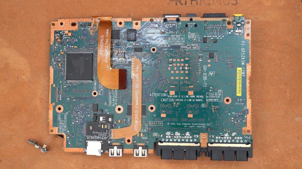
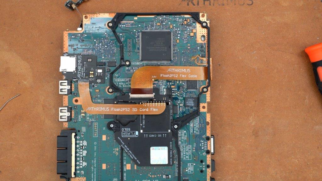
Flip the motherboard over and fold the flex cable over until you have it aligned and then solder down the left side anchor point as shown below.
Then simply solder all of the points marked below, again being careful to not leave any bridges or shorts.
After that you can solder the remaining 2 anchor points to act as a strain relief for the flex cable.
Power Board Install:
The power board install location on the bottom side of the PS2 motheboard is marked below.
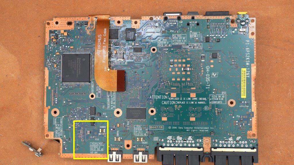
Step 1:
Position the Power board in the location shown below. (Note that some PS2 motherboards may have a larger black resettable PS11 fuse. If you have one of these consoles, you may need to use a file to widen the opening on the areas marked below so the power board can fit into place properly.)
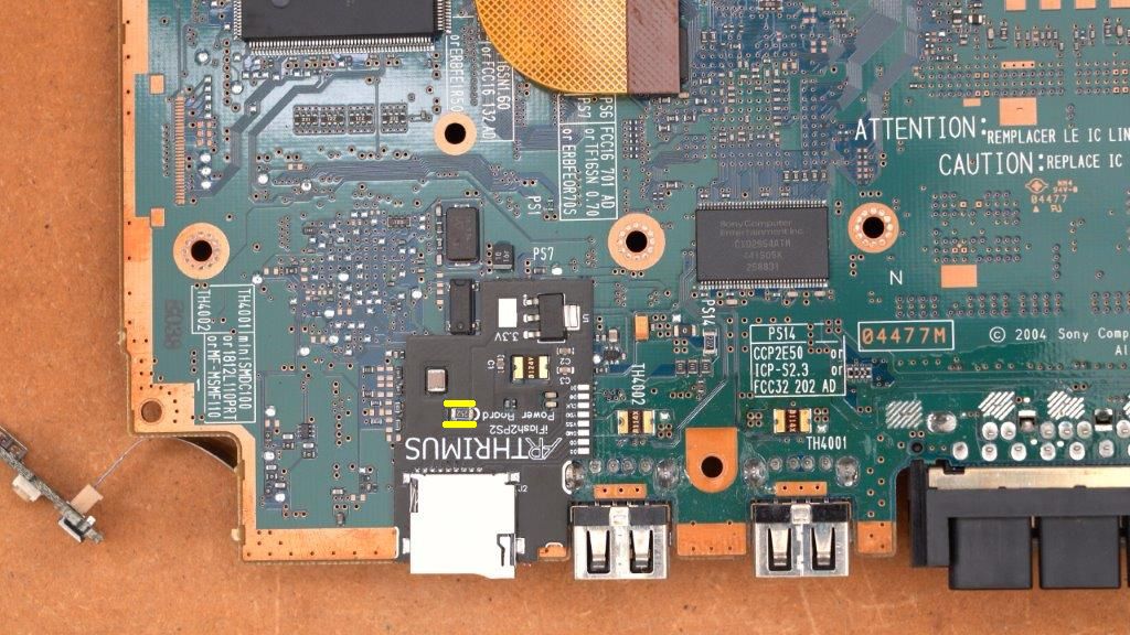
Step 2:
Solder the power point and the ground anchor points marked below.
SD Card Extender Flex Install:
Step 1:
Rotate the PS2 motherboard and add solder to the far left pad of the power board as shown below.
Step 2(Original Kit Design):
Position the SD Card Extension Flex cable as shown below, and tack it in place using the pad that we added solder to in step 1. Then solder all of the remaining pads.
Step 2(New Kit Design):
Flip open the FFC connector latch.
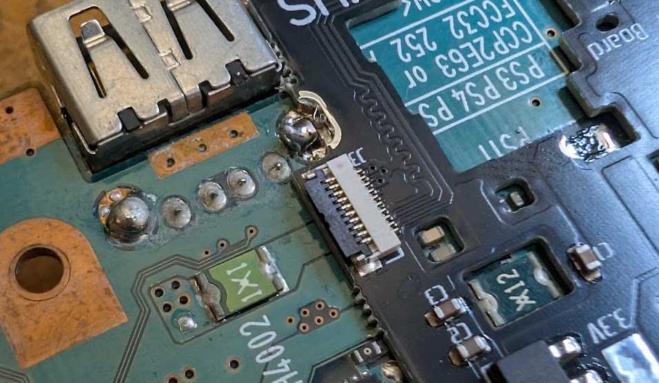
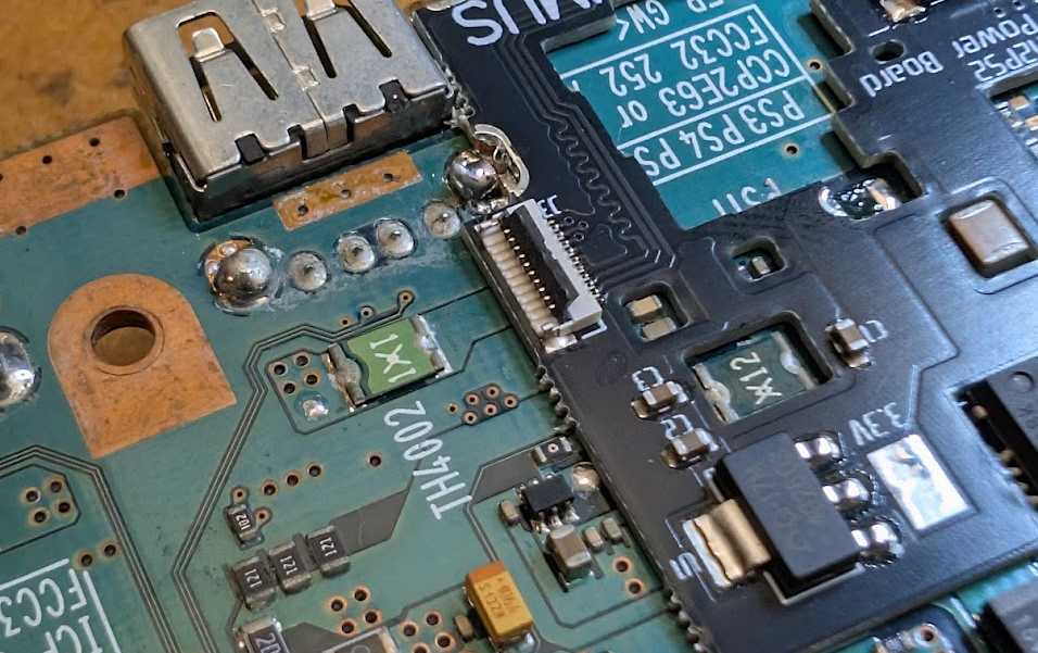
Insert the SD card flex cable into the FFC connector.
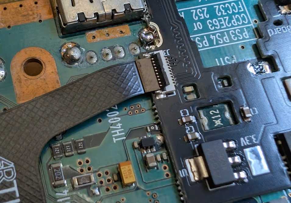
Close the FFC connector latch.
3D Printed Frame install:
New Design:
The new 3D printed mounting bracket consists of a single center bracket for the iFlash Solo, 5 M2 nut standoffs, and 2 3D printed screw standoffs.
The standoffs are connected together with small plastic tabs. You need to break the tabs to separate the standoffs.
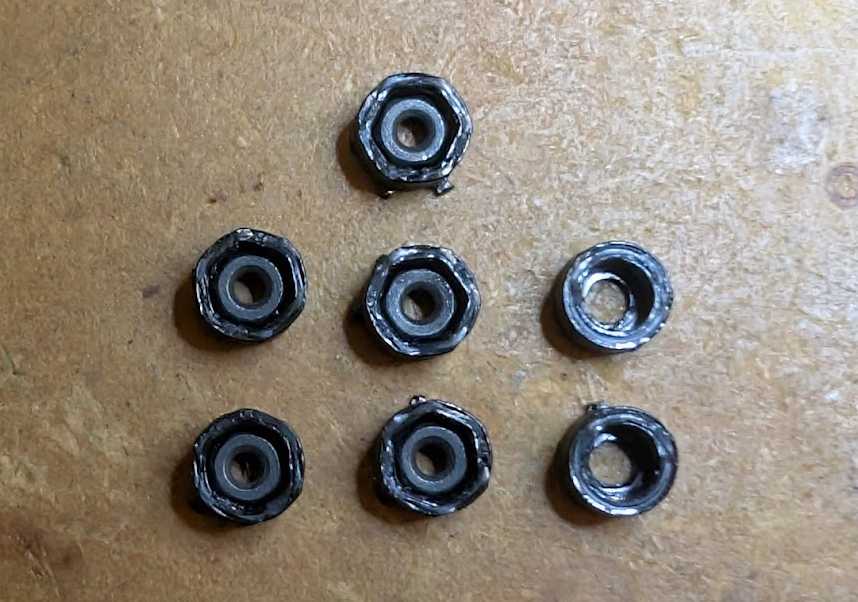
The iFlash bracket and the 2 screw standoffs must be attached using the PS2’s original M2 screws. The 5 M2 nut standoffs must be attached using the PS2’s optical drive screws and the single M2 screw under the optical drive spindle motor as shown in the image below.
Old Design:
Now we need to install the 3D printed frame to hold the top shield, heatsink, and disc drive in place. The frame mounts to the bottom of the PS2 motherboard as shown below.
Step 1:
Make sure that the main iFlash2PS2 Flex cable is routed under the frame through the provided cutout on the frame, and the SD Card extender flex is routed above the frame as shown below.
Step 2:
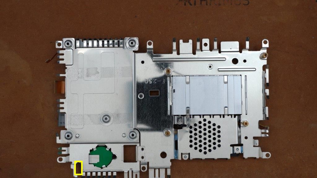
Place the top shield face down on your workbench making sure to hold the disc drive assembly in place as you do it so it is not damaged, then lower the motherboard onto the shield as shown below. Make sure that the power/reset board flex cable passes through the area marked below, and does not get pinched by the top shield.
Step 3:
Install the heatsink screws in the 4 locations marked below.
Step 4:
Carefully flip the motherboard back over making sure to hold the disc drive assembly in place while you do this so it is not damaged.
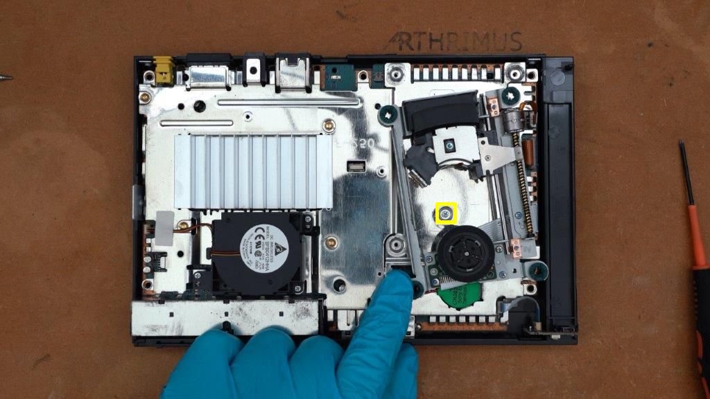
Then carefully slide the disc drive assembly out of the way and install the screw marked below.
Then slide the drive assembly back into position and install the remaining 4 screws marked below and reconnect the 3 disc drive flex cables and the battery and fan cables.
Now set your motherboard aside and get ready to prep your iFlash board.
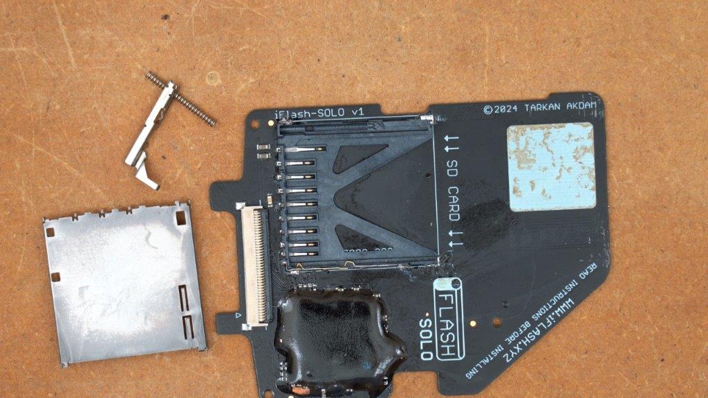
iFlash Solo Prep:
In order to install the iFlash Solo, you must first do some prep work. The SD card slot on the iFlash needs to be removed so we can solder the extender flex in place. The following procedure is probably the easiest option for most people.
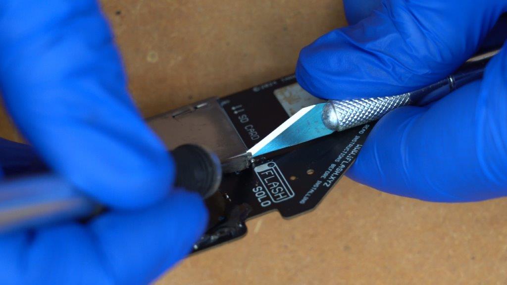
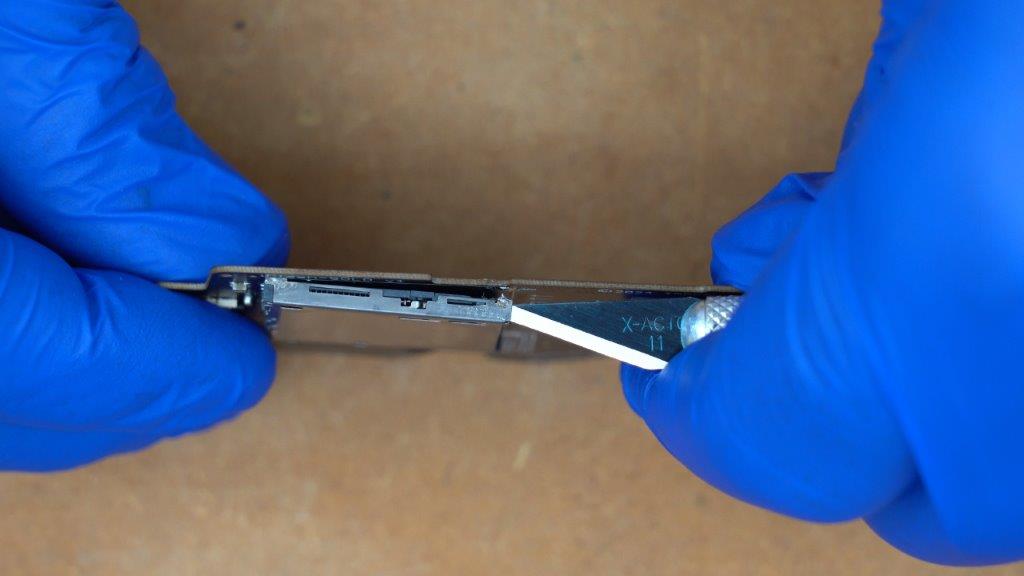
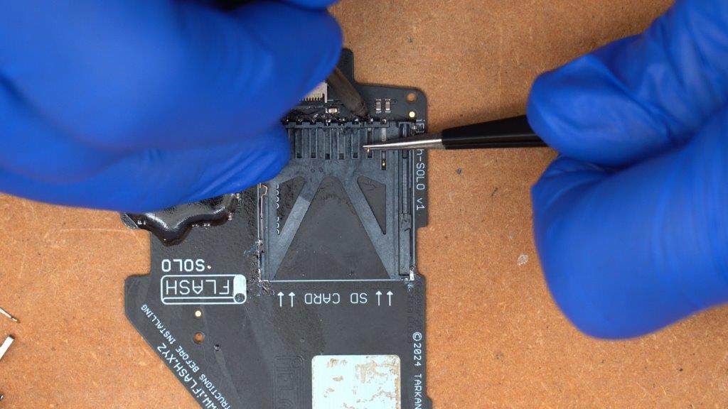
Step 1:
Insert a hobby knife, or some other similar thin tool between the metal shield and the plastic inner frame of the SD Card slot in the corner closest to the iFlash logo.
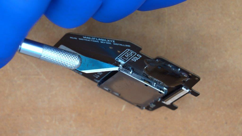
While using your soldering iron to melt the solder on the pad that you are working on, twist and lift the shielding using your hobby knife to free it from the iFlash board as shown below.
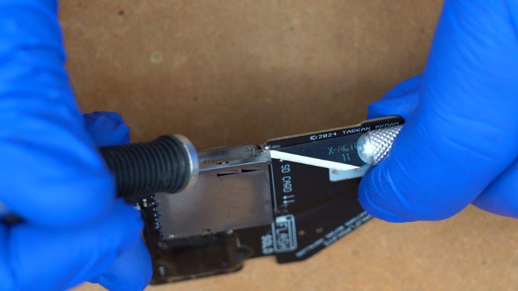
Step 2:
Once you have successfully freed the first corner, rotate the iFlash board and insert your hobby knife between the shielding and the plastic frame on the opposite side of the SD card slot.
As with step 1, use your soldering iron to melt the solder and use your hobby knife to bend the metal shielding away and free it from the pad on the iFlash board.
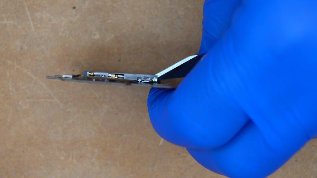
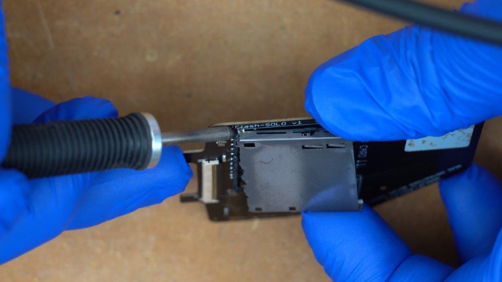
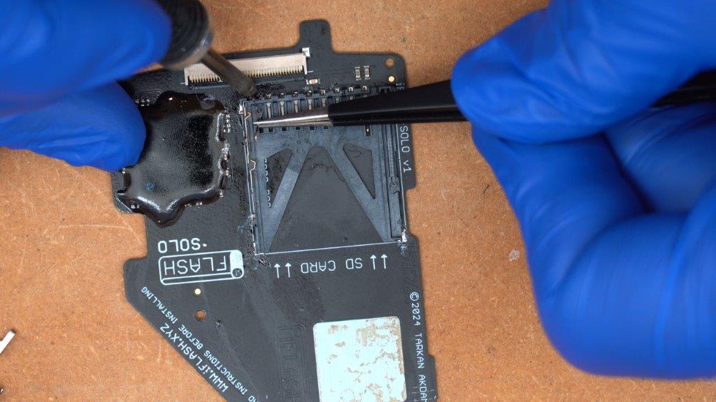
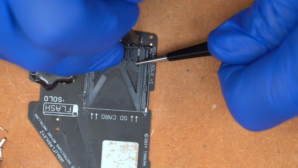
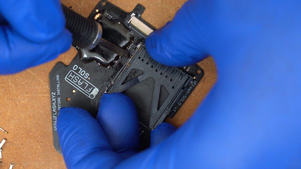
Step 3:
Move to the corner of the SD card slot closest to the 40 pin ZIF connector, and use your soldering iron to heat the solder on the metal shield while you gently pry the shielding upward to free that corner from the iFlash board as shown below.
Step 4:
Move to the final corner and once again use your soldering iron to melt the solder and gently pry the metal shielding completely off of the iFlash board.
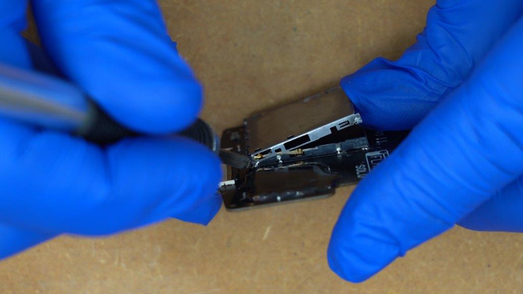
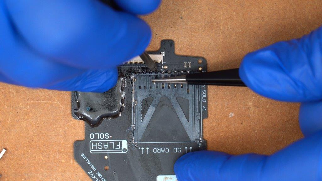
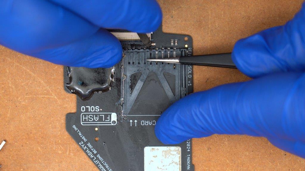
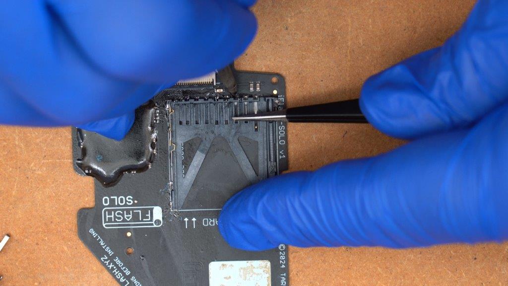
Step 5:
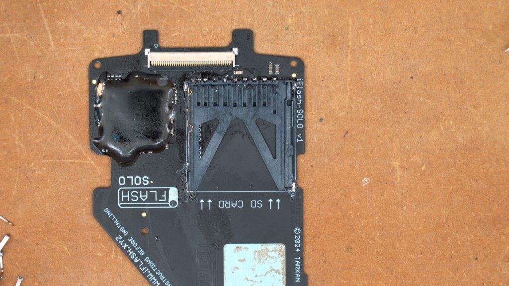
Using your soldering iron to melt the solder on each of the pads for the contact pins of the SD card slot, use some tweezers to pull out each pin as shown below. Be careful to fully melt the solder before you pull each pin out, as not doing so could damage the pads on the iFlash board rendering it useless. Also take care not to accidentally melt the 40 pin ZIF connector with your soldering iron.
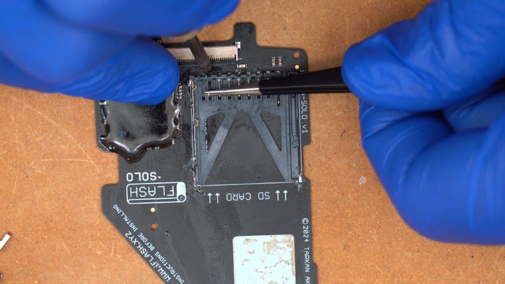
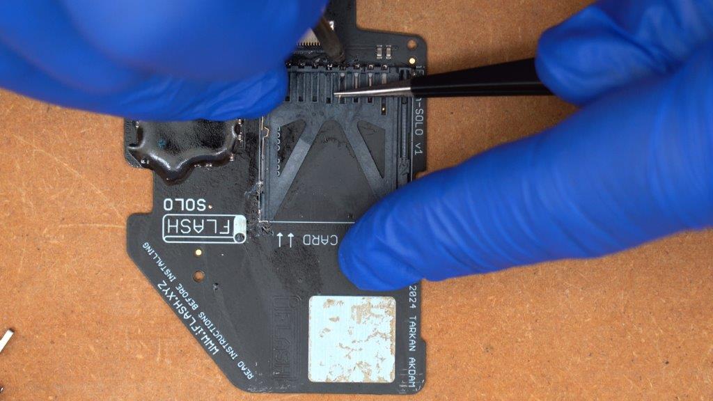
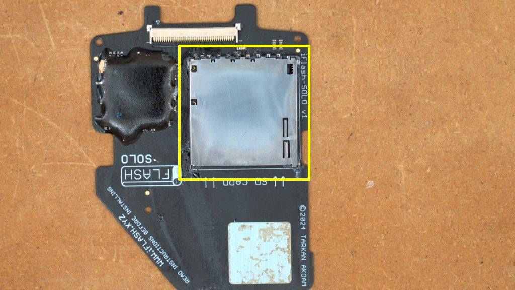
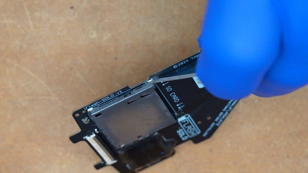
Once you have removed all of the pins the iFlash board should look like this.
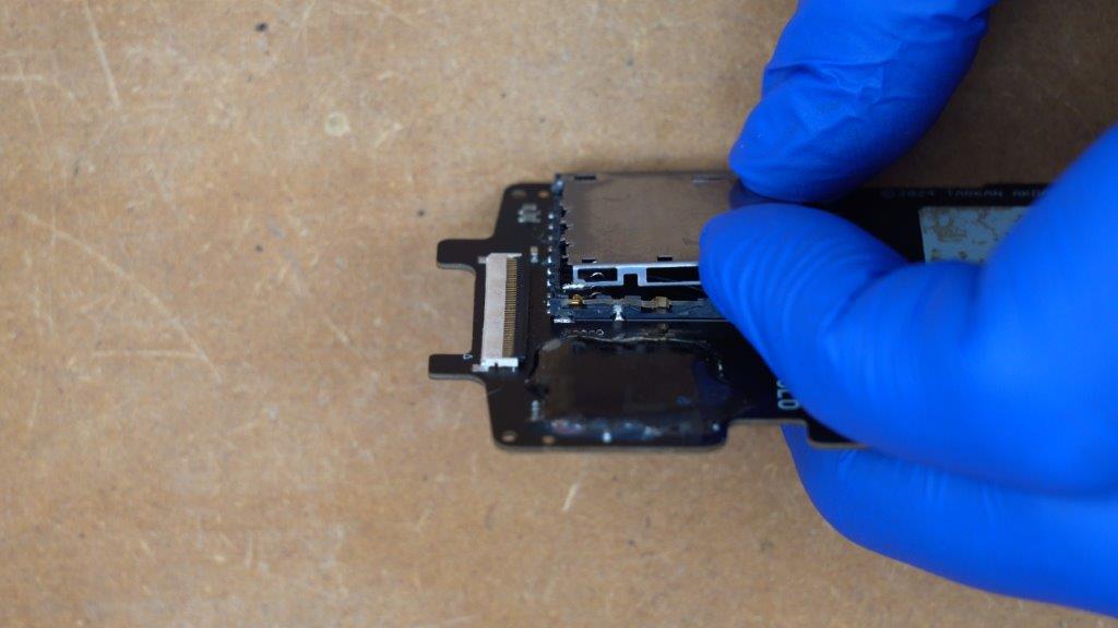
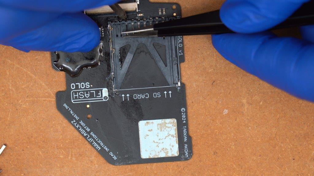
Step 6:
Use your soldering iron to melt the solder connecting the SD card switch pins while gently prying up the plastic frame of the SD card slot as shown below.
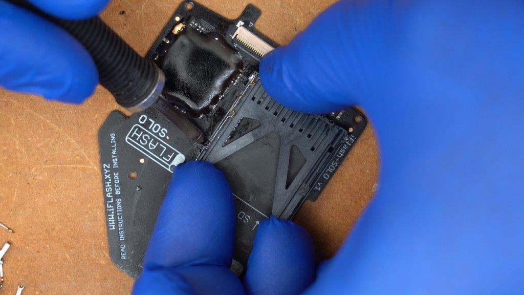
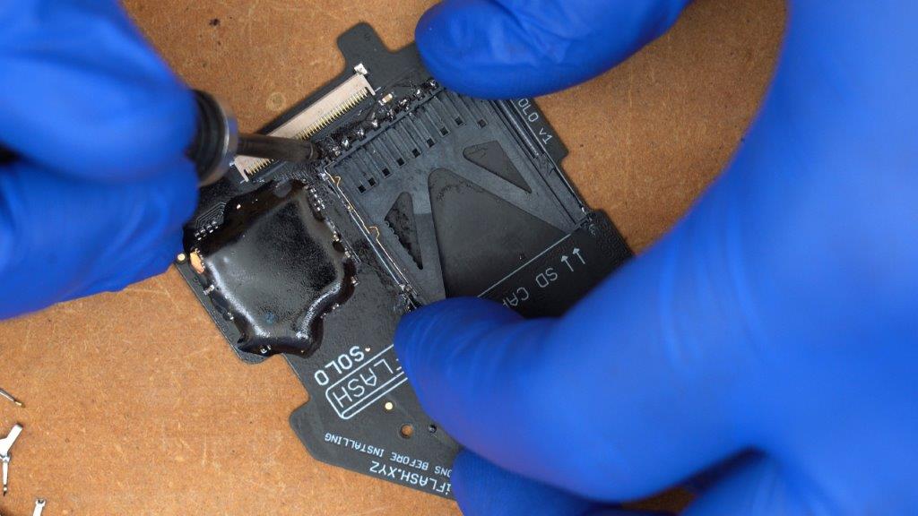
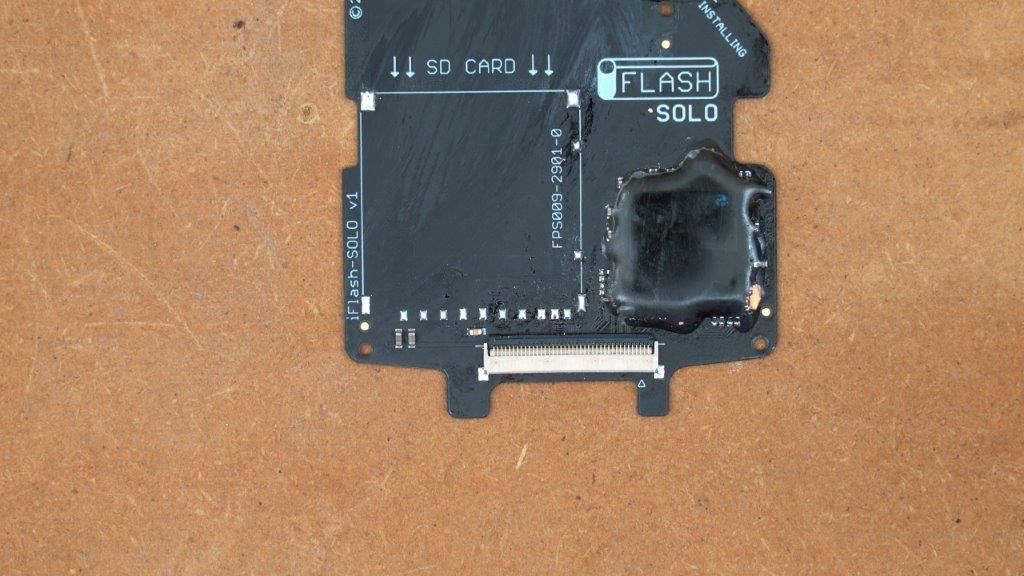
The plastic frame should now lift free, leaving your iFlash Solo board looking like this. You will probably want to use some fresh solder to clean up and prep each of the pads for the extender flex install.
iFlash Solo Install:
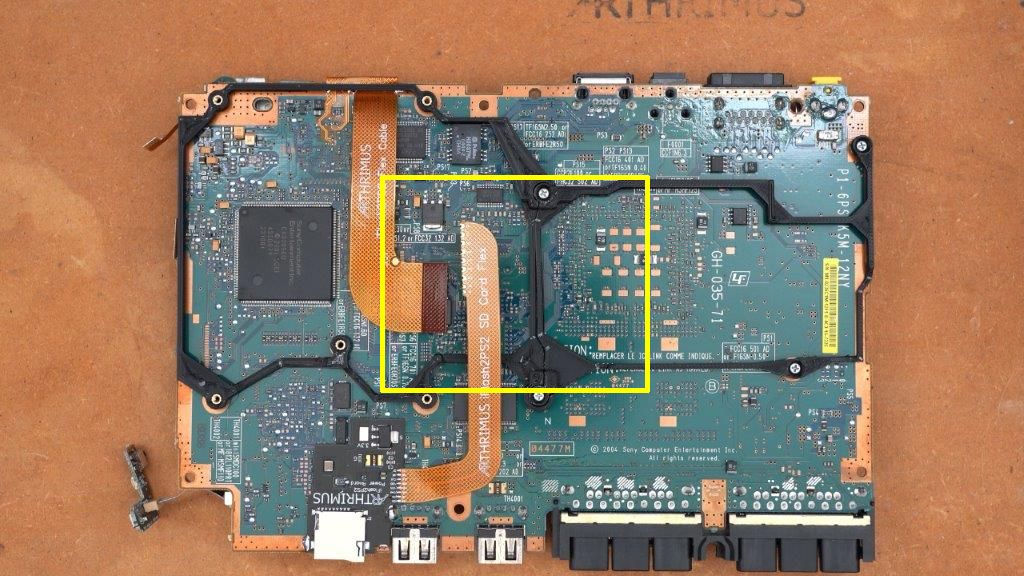
Now that the iFlash is prepped, we need to install it into the PS2. We’ll be working in the area marked below.
Step 1
Connect the iFlash2PS2 flex cable to the iFlash Solo 40 pin ZIF connector, then snap the iFlash solo into the 3D printed frame as shown below.
Step 2:
Once the iFlash is snapped into place, the SD extension flex should line up with the pads on the iFlash Solo board where the SD card slot was previously mounted. Simply solder each pad of the SD card extension flex to the iFlash Solo board as shown below.
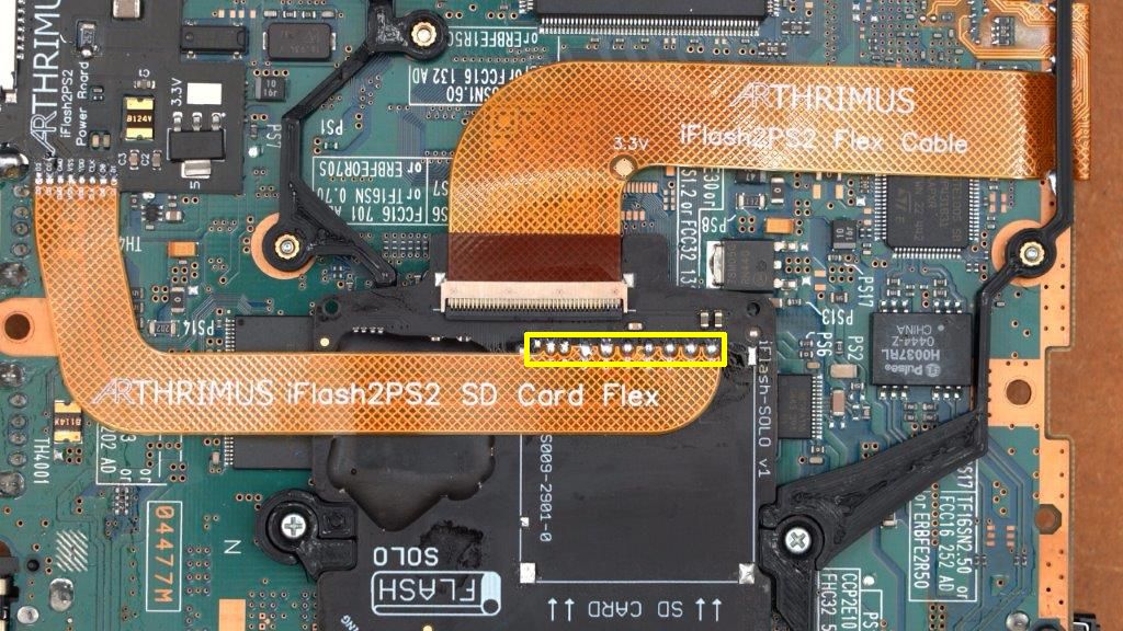
Note that there is one pad at the very far left of the marked area that is not soldered to the extension flex. That pad is should be left disconnected as it was part of the switch mechanism of the old SD card slot and is no longer relevant.
At this point you should plug your PS2 in and test the iFlash with an SD card. I would recommend using FreeMCBoot to launch the HDD Manager utility and see if your SD Card is detected.
Capacitor Mod:
Thanks to R3Z3N and PCM720 we now have a modification to the iFlash install process that vastly improves SD card compatibility and SD card detection on hot reboot. The mod involves adding 4 100pf 0603 capacitors to the PS2 motherboard. This mod has been tested and enables consistent compatibility with a range of previously incompatible SD cards including the SanDisk 1.5tb sd card that was previously determined to be incompatible.
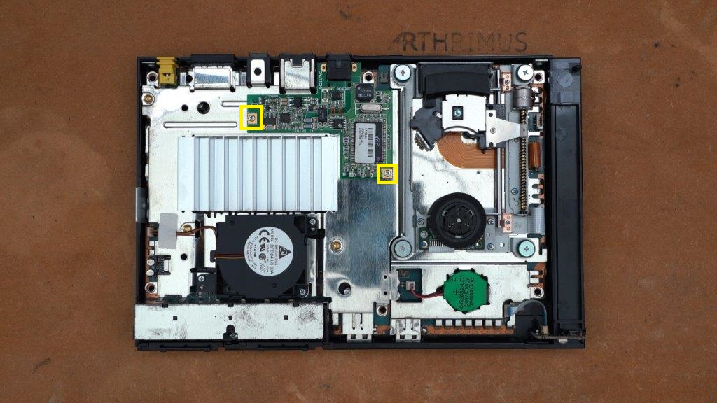
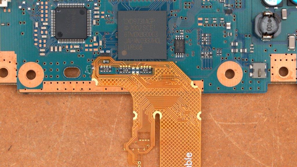
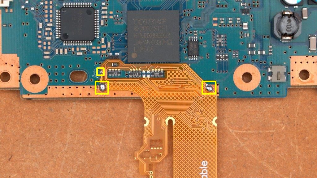
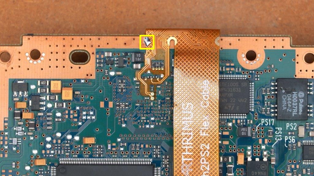
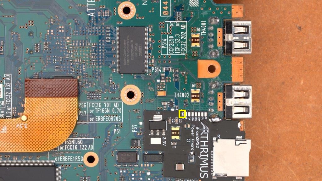
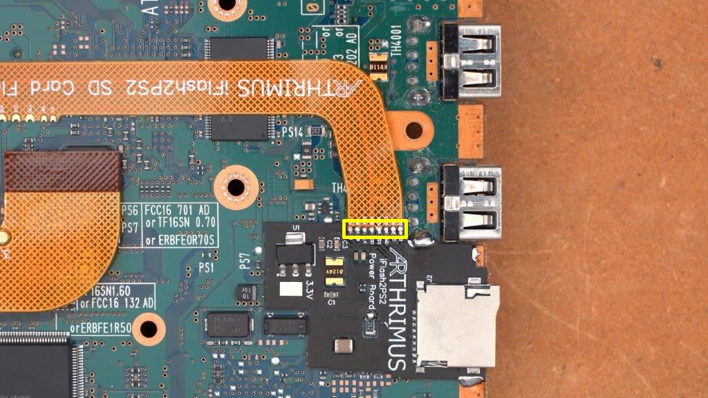
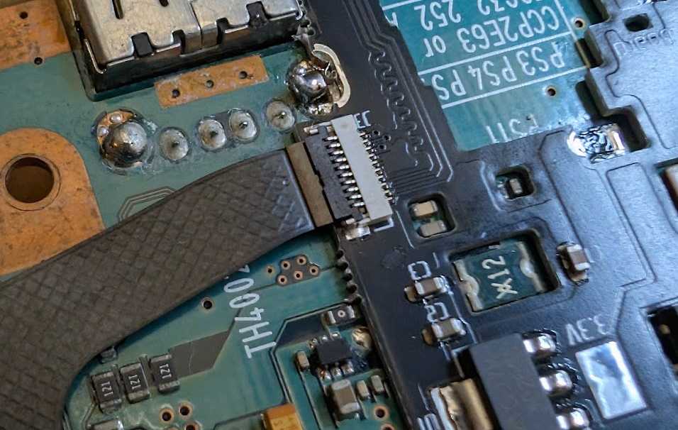
On the top of the motherboard you need to install a single capacitor. The capacitor needs to be soldered to the two points marked in the image below in yellow. MAKE SURE THE CAPACITOR IS ONLY CONTACTING THE MARKED PADS. If you bridge any of the other pads it will prevent the iFlash from functioning. You can apply kapton tape to the nearby pads to protect them from potential bridging before soldering the capacitors.
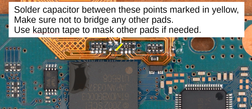
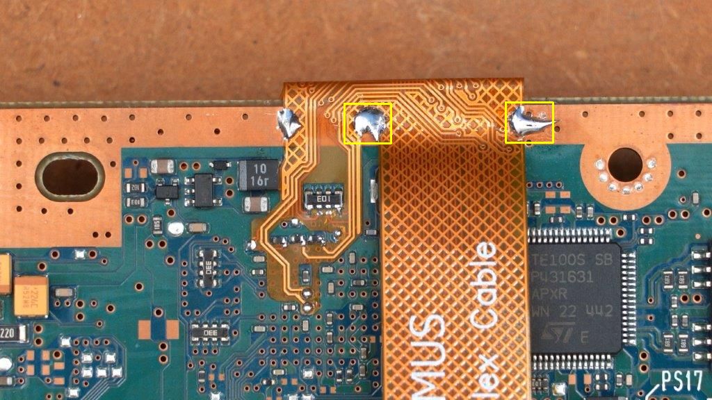
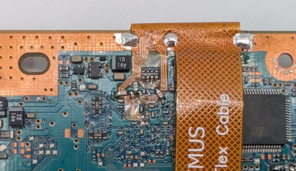
The completed top capacitor install should look like this.
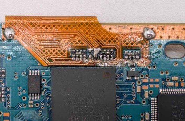
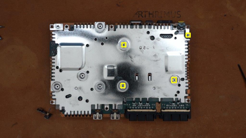
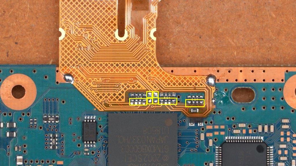
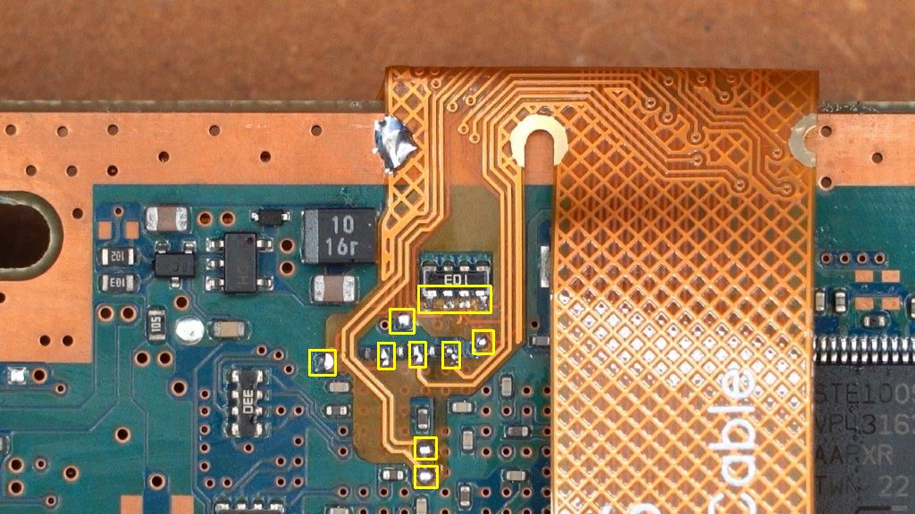
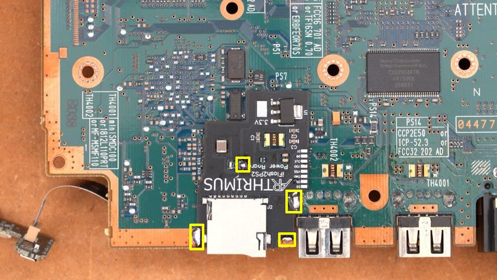
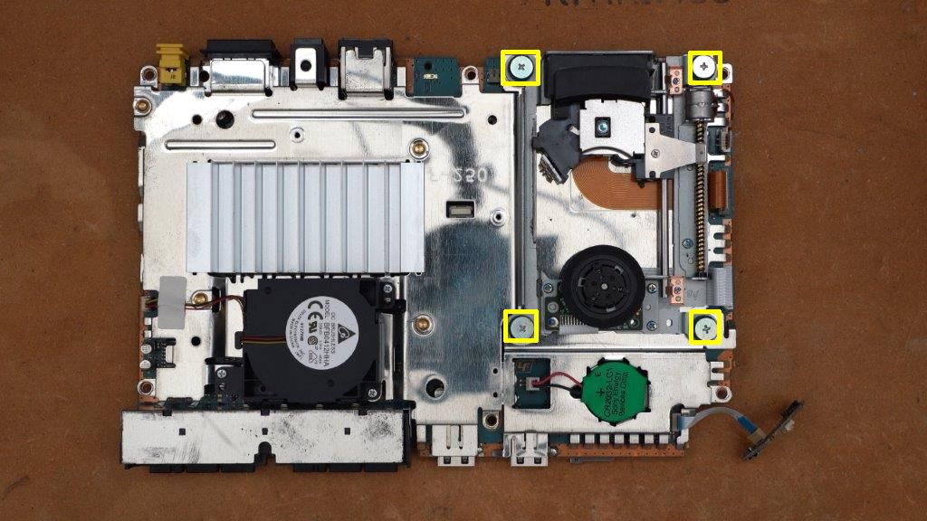
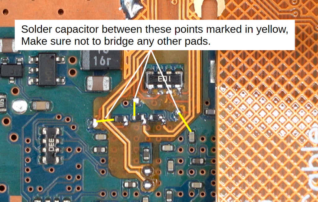
On the bottom of the motherboard you need to install three capacitors. The capacitors need to be soldered between each of the two points marked in the image below in yellow. MAKE SURE THE CAPACITORS ARE ONLY CONTACTING THE MARKED PADS. If you bridge any of the other pads it will prevent the iFlash from functioning. You can apply kapton tape to the nearby pads to protect them from potential bridging before soldering the capacitors.
The completed bottom capacitor install should look like this.
Reassembly:
To reassemble the console simply do the disassembly steps in reverse.
Step 1:
Reinsert the motherboard into the top shell by inserting the front of the motherboard first, then rotating the back of the motherboard down into the shell. Make sure that the motherboard seats fully inside the bottom shell before proceeding. You also need to reinstall the power/reset board. It simply snaps into place in the molded tabs on the bottom shell.
Step 2:
Install the modem using the 2 screws marked below.
Install the screw located by the controller ports.
Step 3:
Install the top shell by aligning the front of the top shell with the bottom shell, then rotating the rear of the top shell down towards the bottom shell until they are flush, then snap the 2 halves of the shell together.
Step 2:
Flip the PS2 over and install the 6 screws marked below.
Then install the screw convers as marked below.
You’re done! Congratulations, you have successfully installed the iFlash2PS2 kit!