MAV-NUS Install Instructions
The following guide will show you how to install the N64RGBv1 on any N64 motherboard with a MAV-NUS or AVDC-NUS chip.
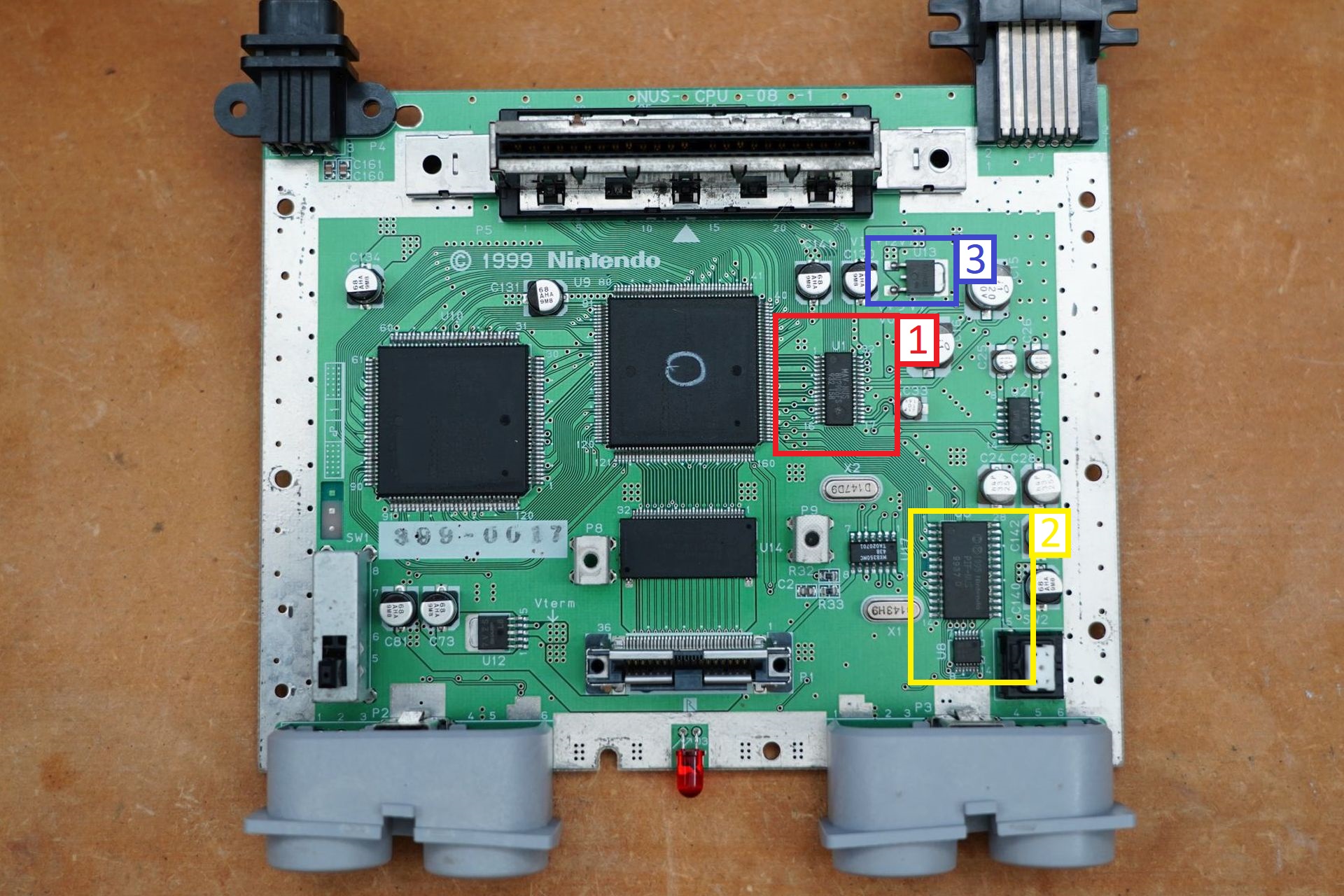
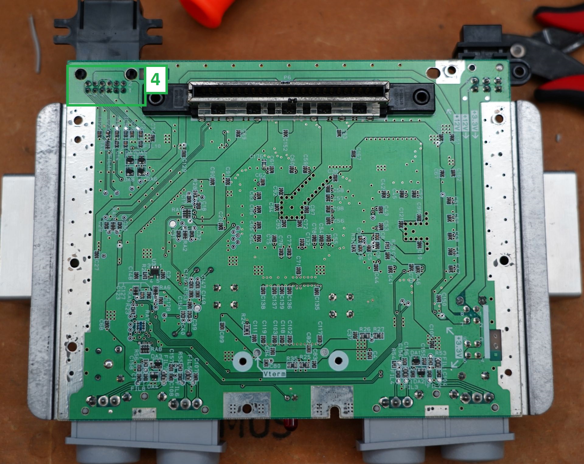
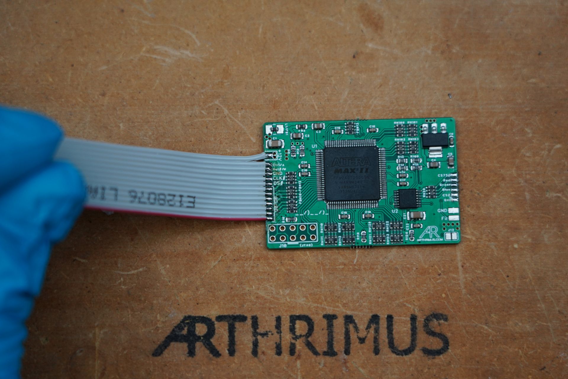
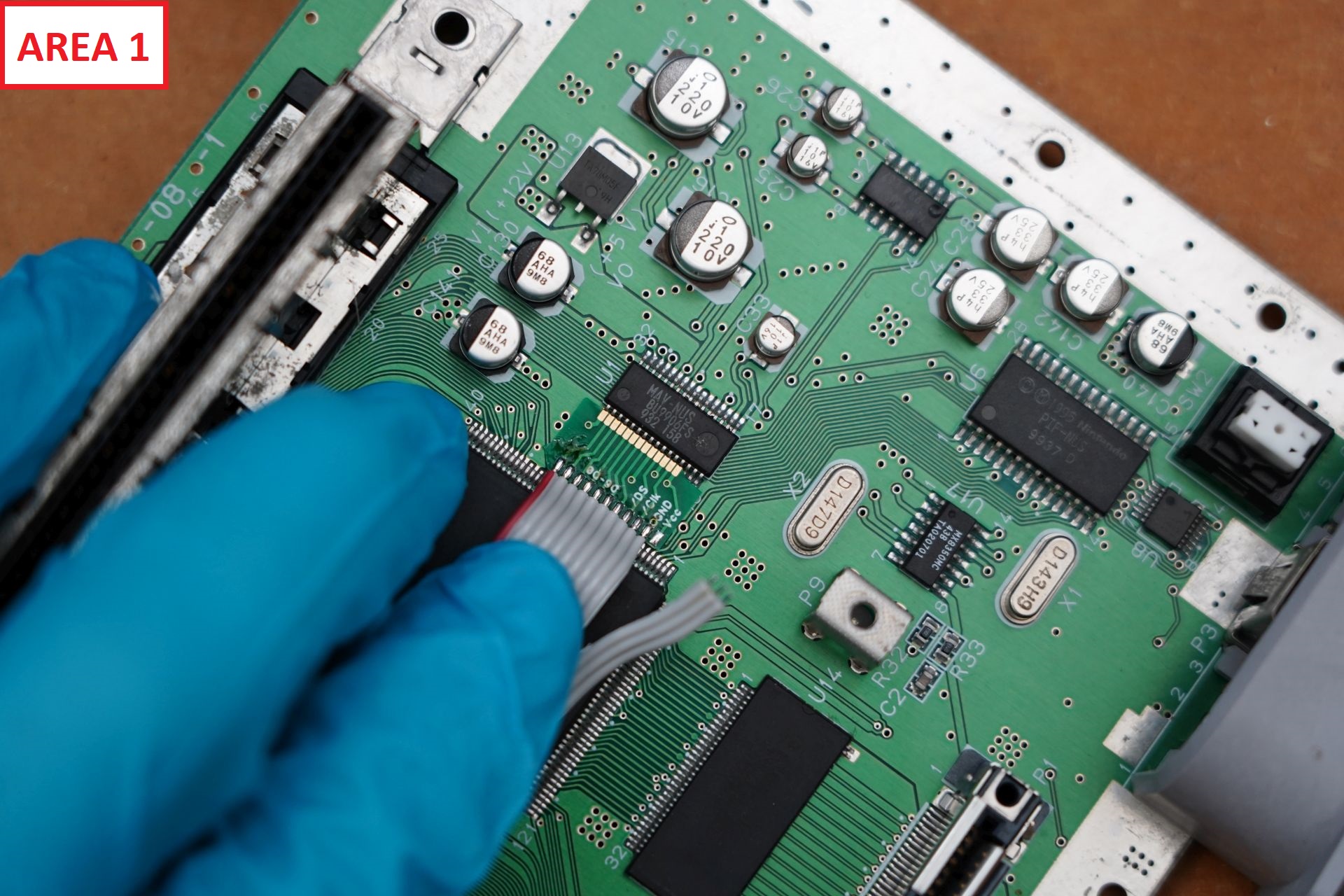
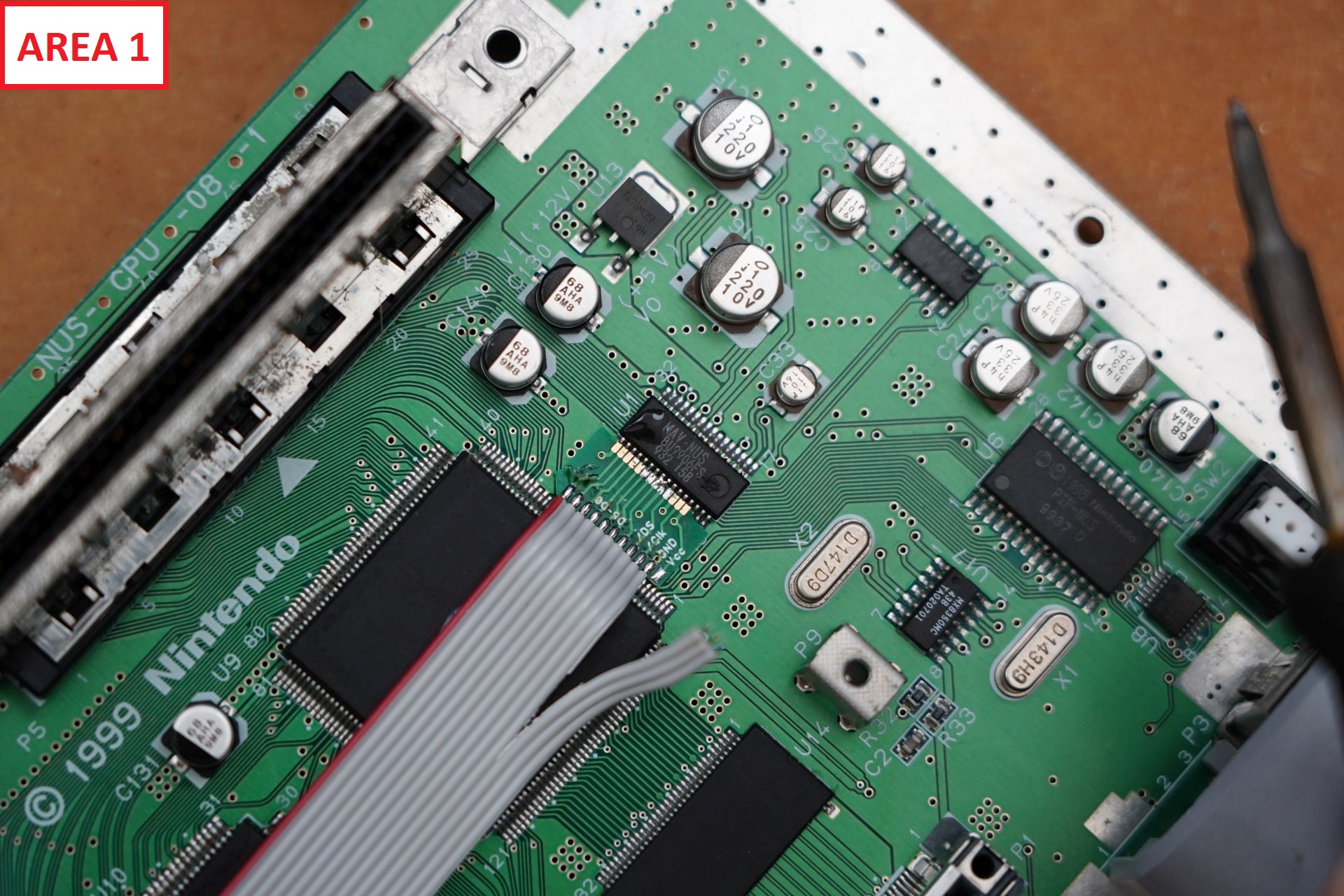
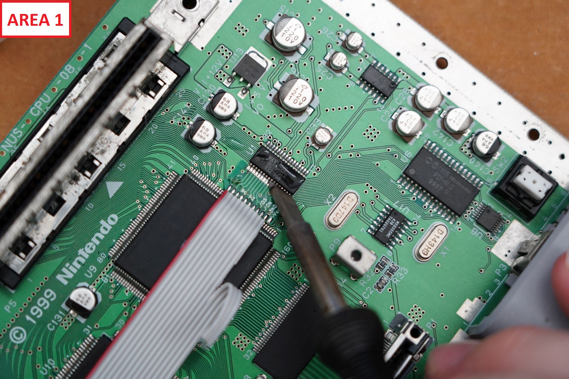
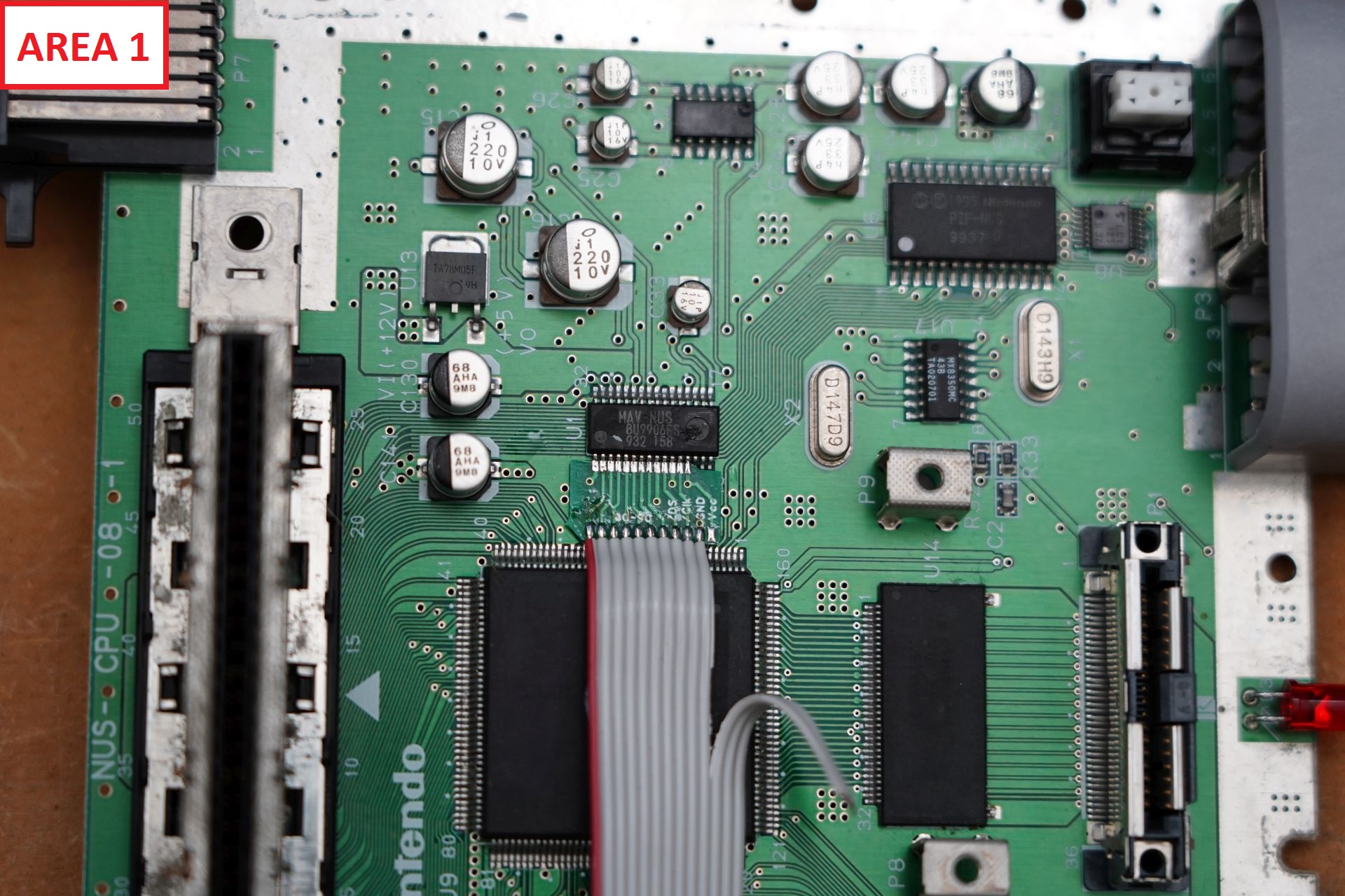
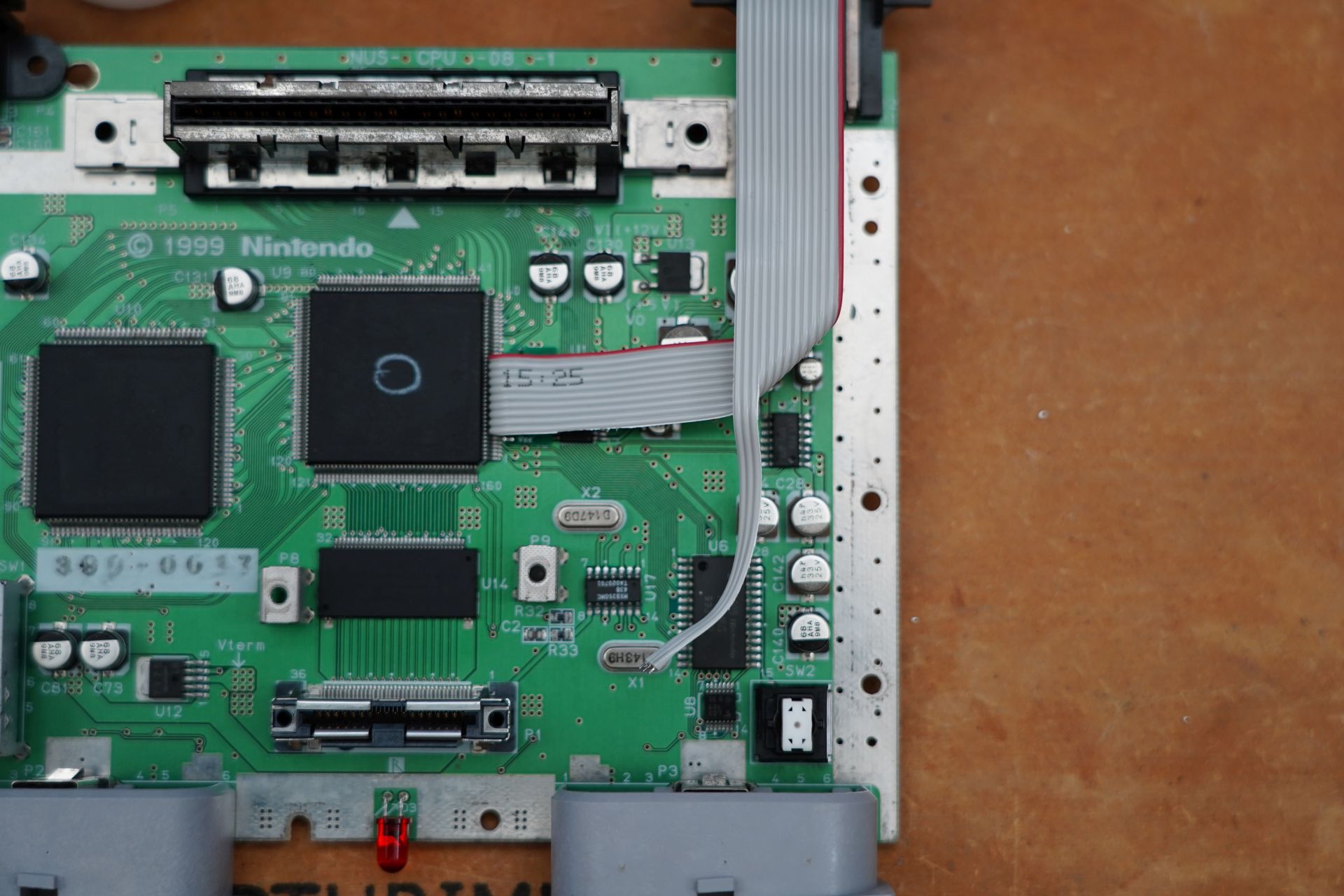
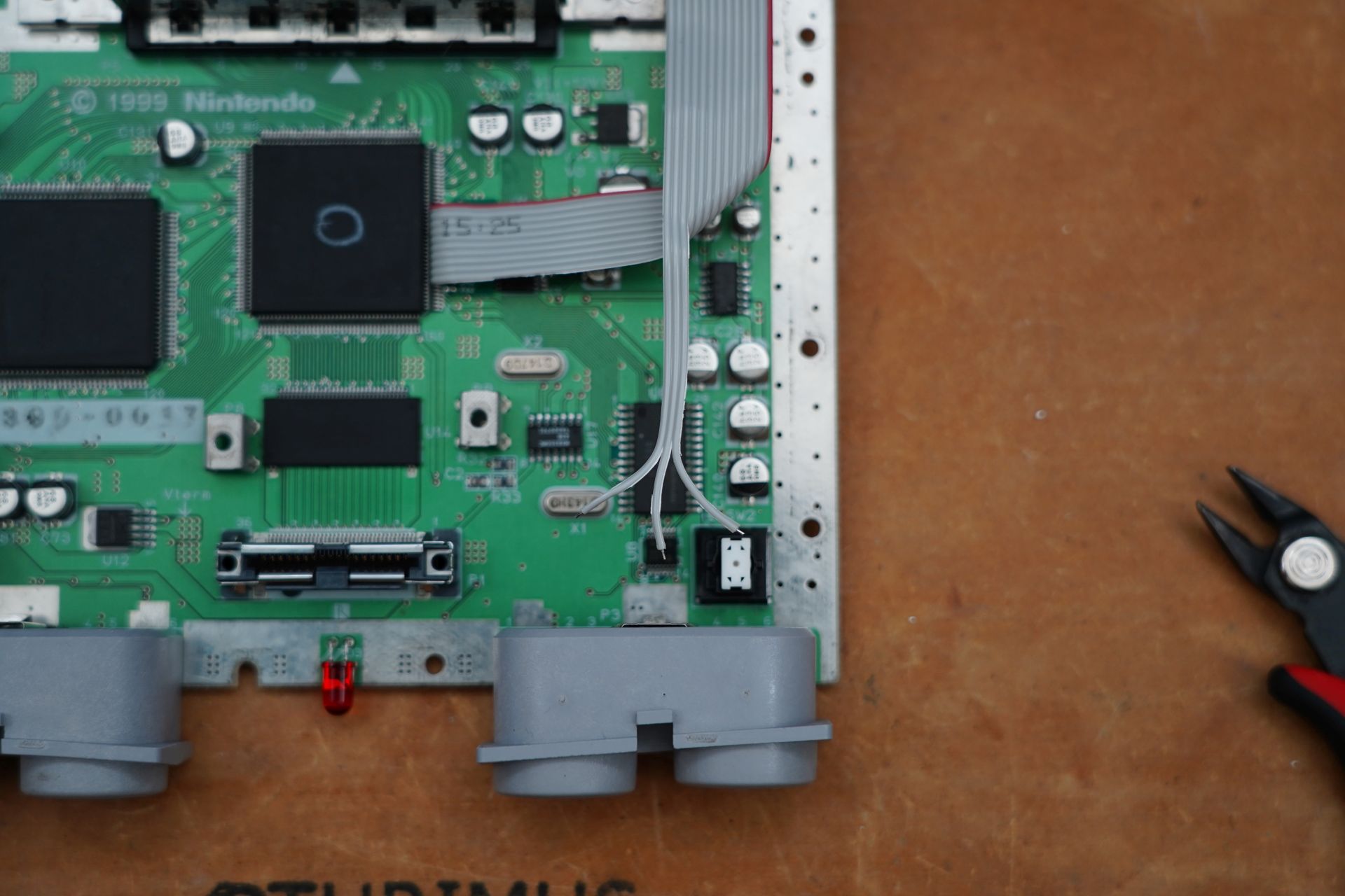
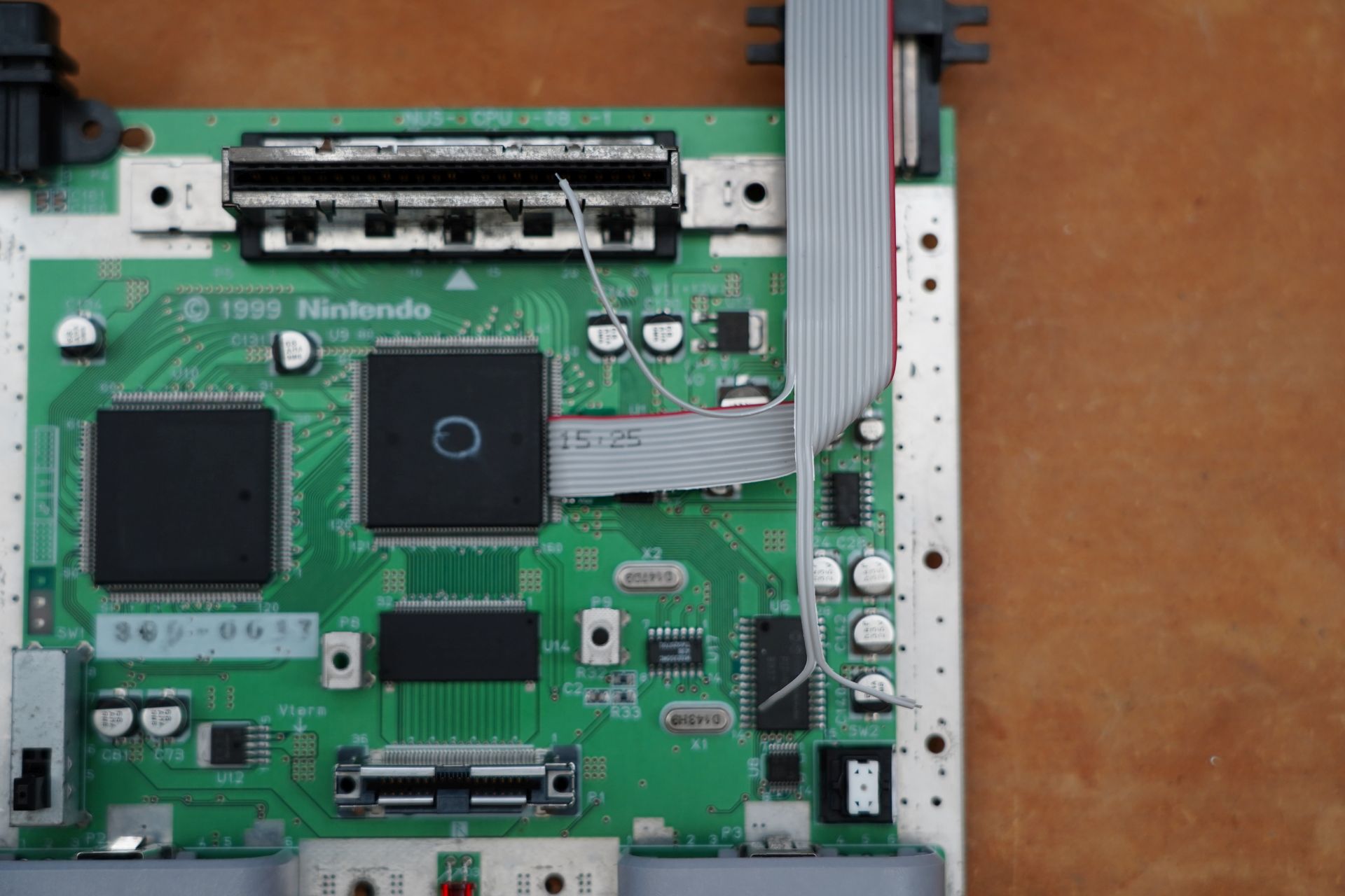
Here is an overview image of the areas of the N64 motherboard that we will be working on.
Step 1:
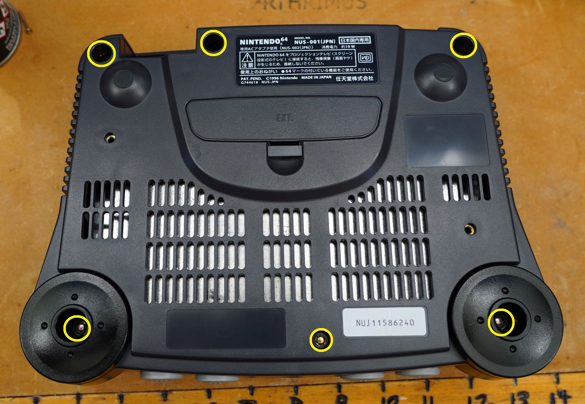
Remove all 6 screws from the bottom of the N64 shell. You will need a 4.5mm gamebit screwdriver.
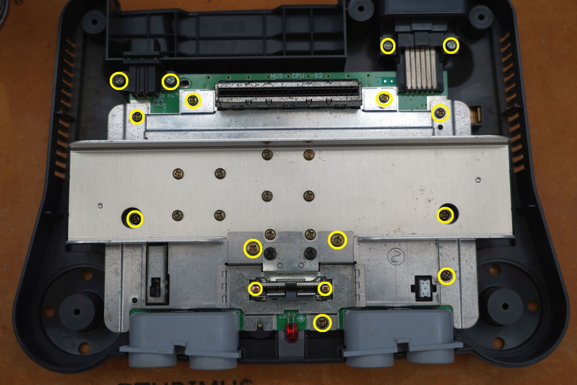
Then remove all of the screws on the shielding marked below.
Step 2:
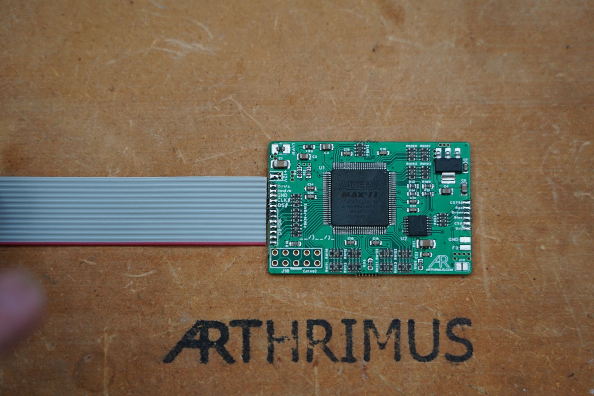
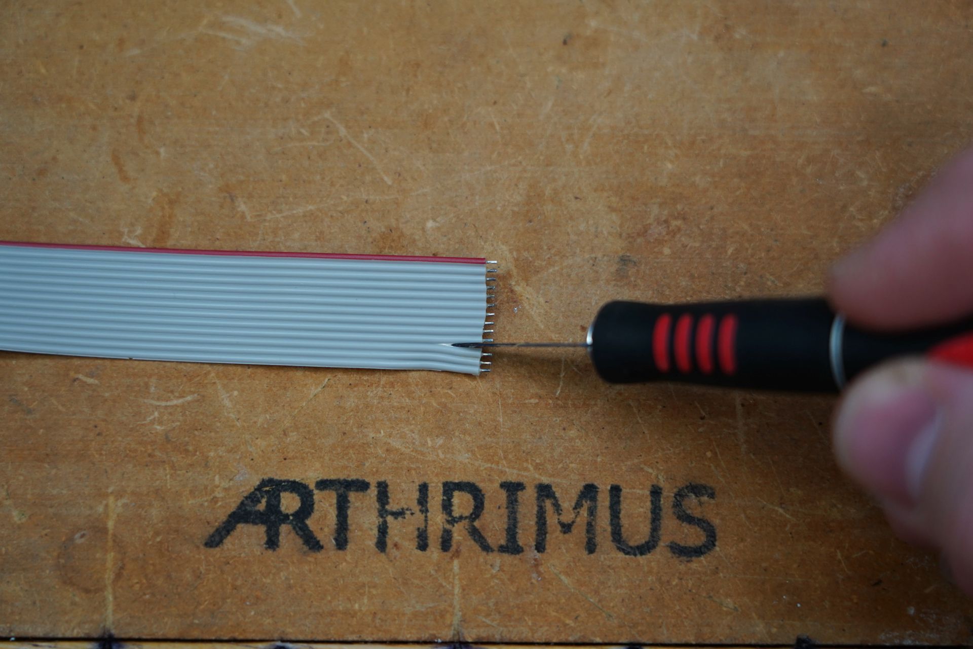
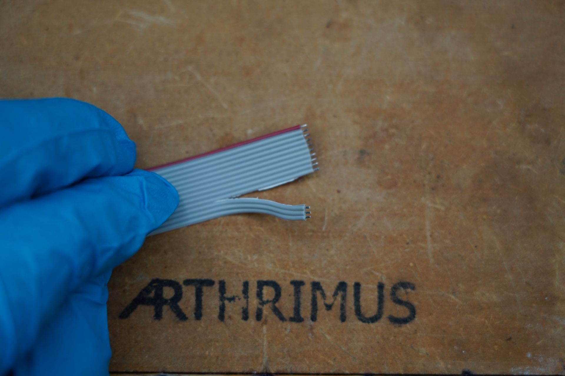
Prepare the provided ribbon cable by removing the last 7 wires from the cable, this will leave 13 wires which should match the 13 pads on the left side of the N64RGBv1 mod as shown in the picture below.
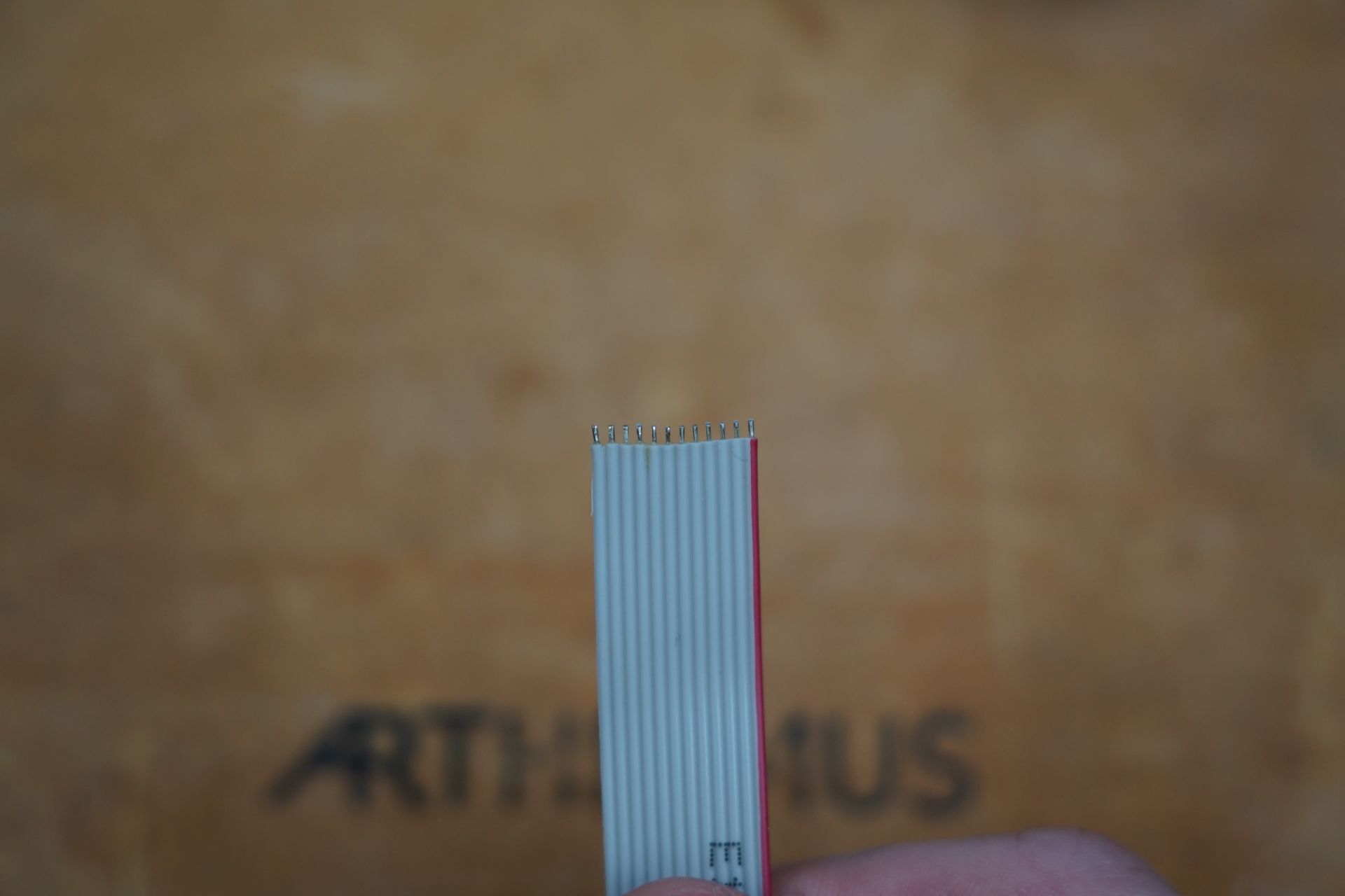
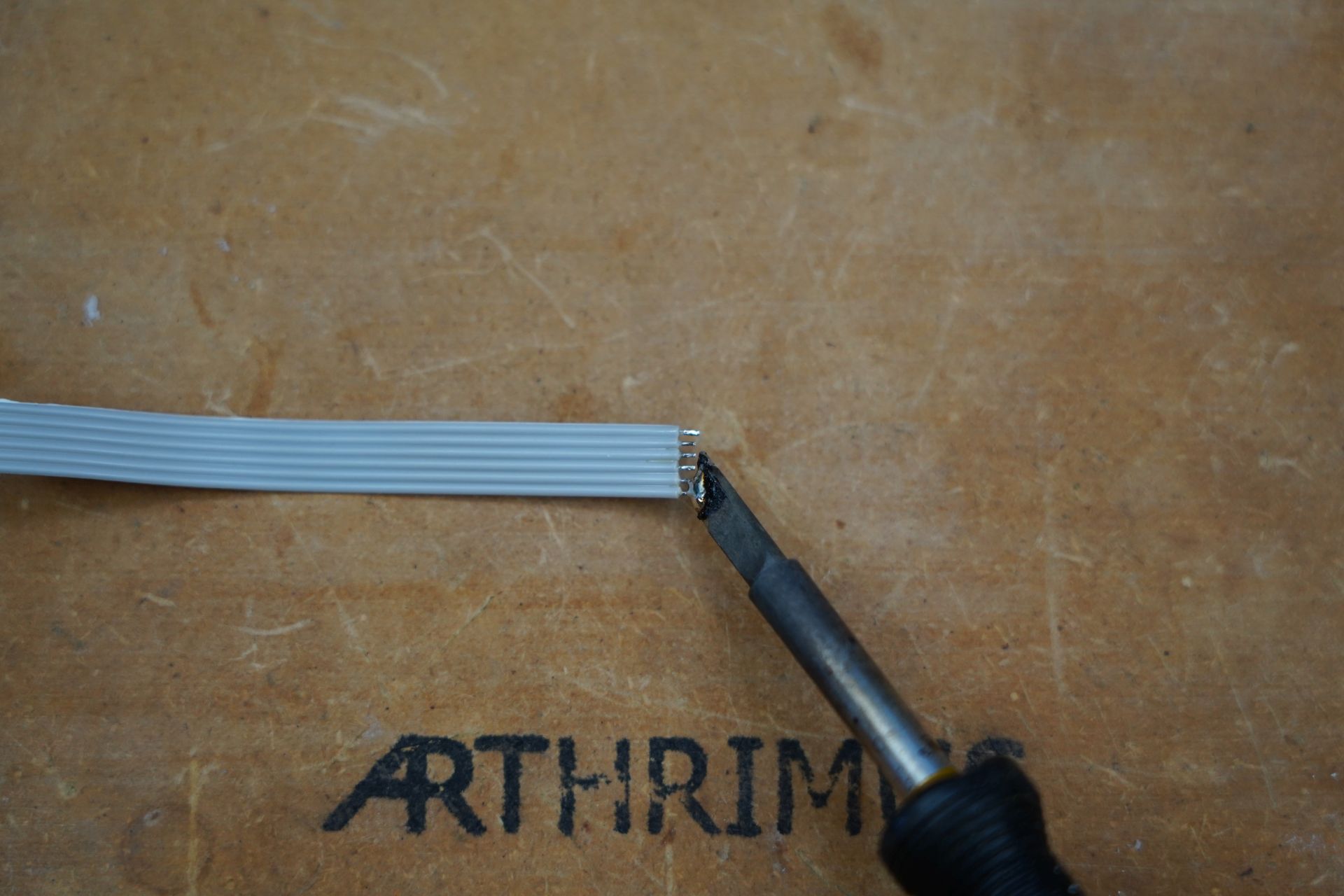
Then you should strip both ends of the ribbon cable and tin all of the wires.
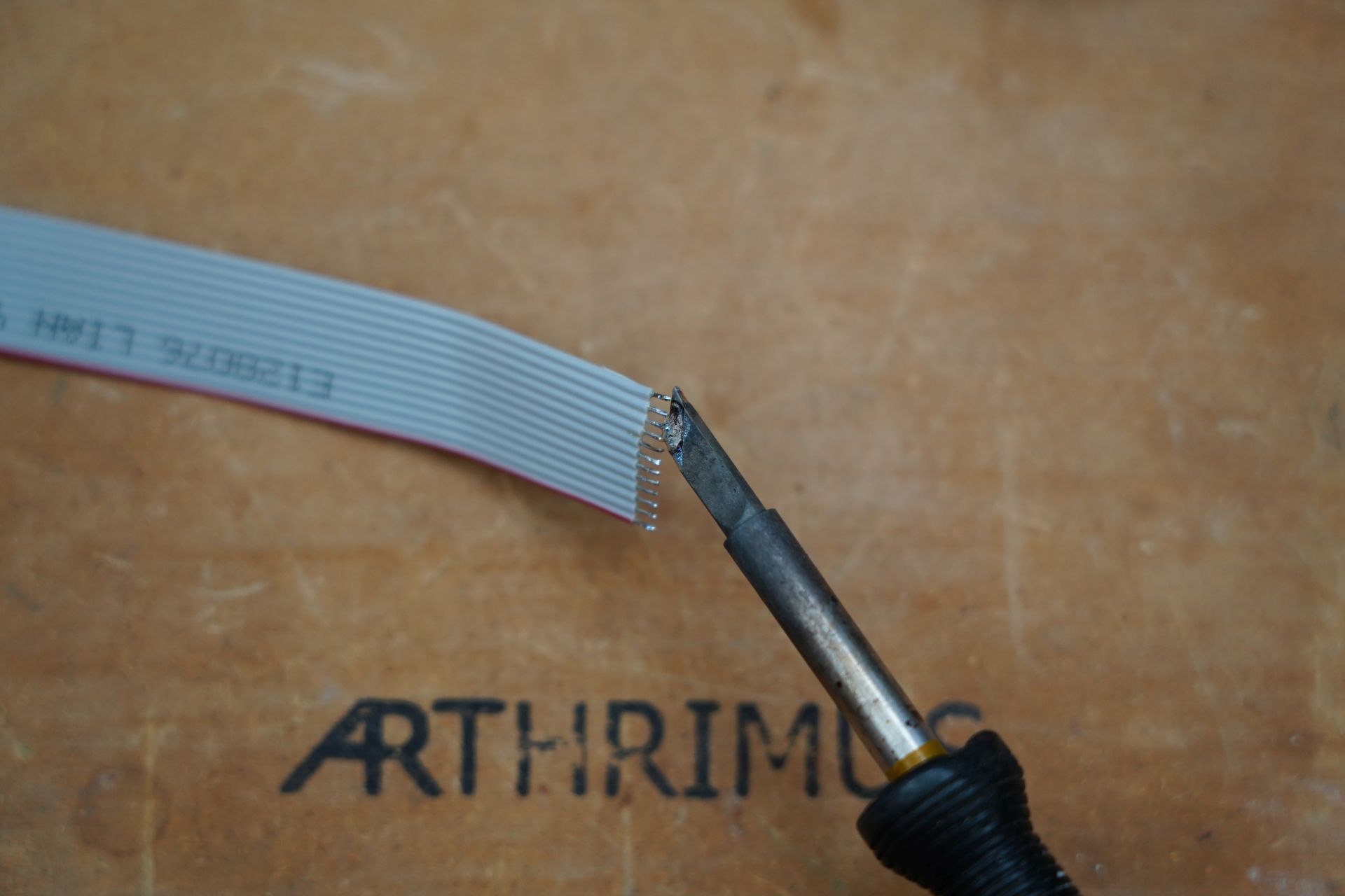
Once the wires are tinned, I recommend trimming them down to about 1/16th of an inch on both sides with some wire cutters.
Step 3:
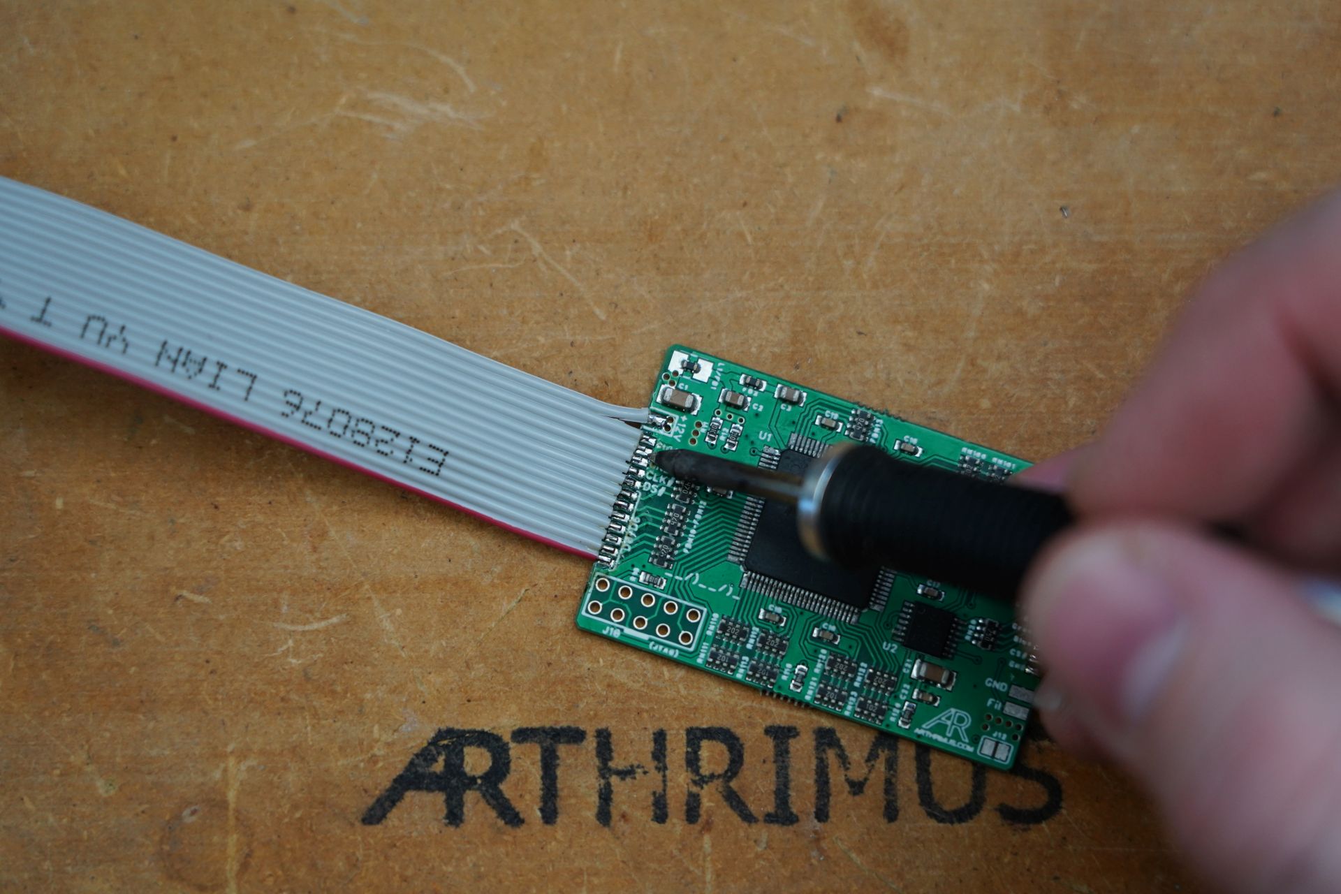
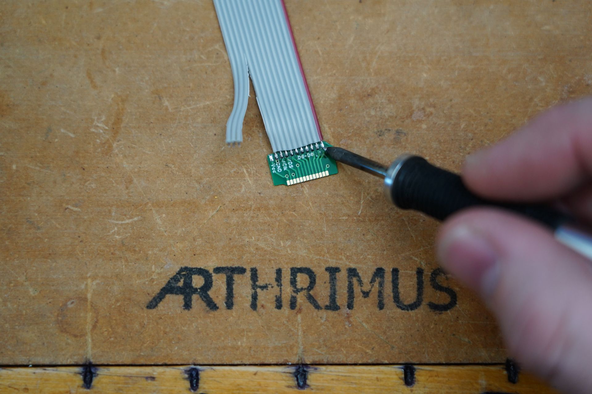
Prepare the N64RGBv1 board for installation by soldering the 13 pin ribbon cable to the board. The side of the ribbon cable with the red stripe should be aligned with the pad labeled D0 that is closest to the bottom of the mod as shown below.
Prep the other end of the ribbon cable by separating the last 3 wires on the side of the cable that does not have the red stripe. These cables will be routed to a different location than the rest, so it’s helpful to go ahead and separate them now.
Prep the MAV-NUS adapter by tinning the pads
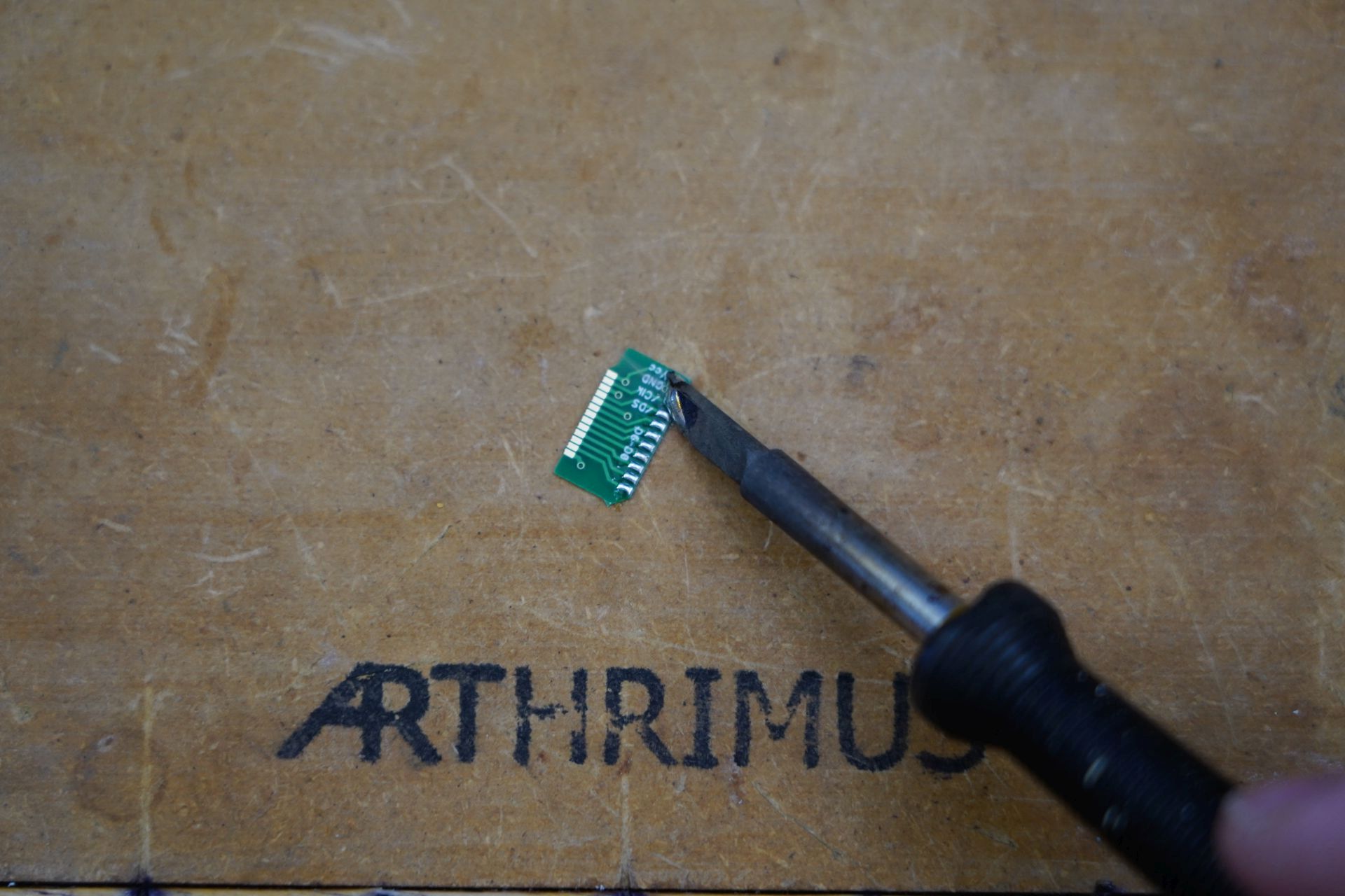
Then solder all of the wires to the MAV-NUS adapter except the pad labeled Vcc. The red stripe should be facing pad D0 as shown below.
Next prep the analog wiring by taking the 7 wires that you separated from the ribbon cable originally, and cutting them in half, and removing one wire leaving a 6 pin ribbon cable as shown below.

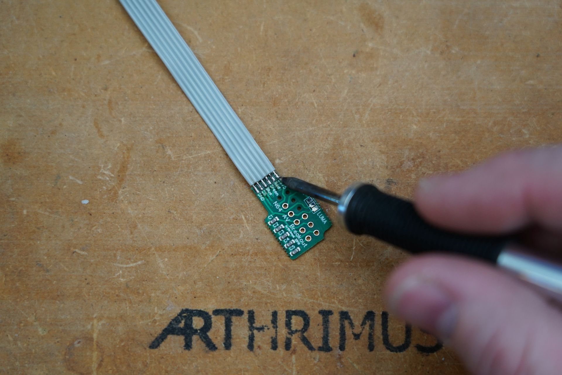
Strip and tin the analog ribbon cable as you did before with the other ribbon cable.
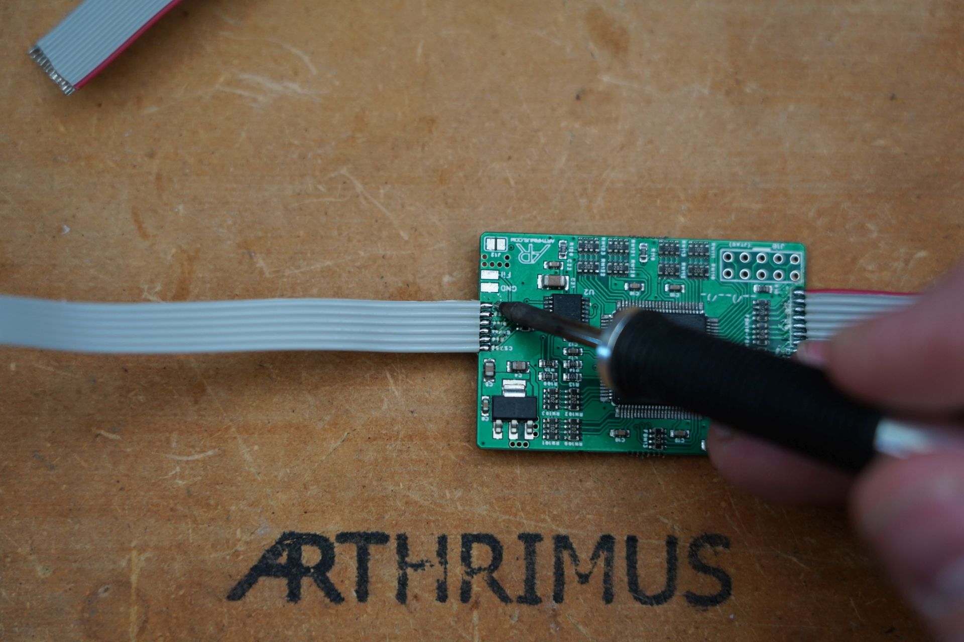
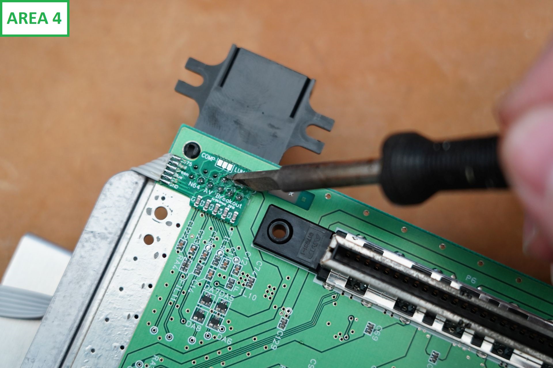
Solder the analog ribbon cable to the N64RGB mod as shown below.
Then take the N64 AV Breakout board and tin the pads.
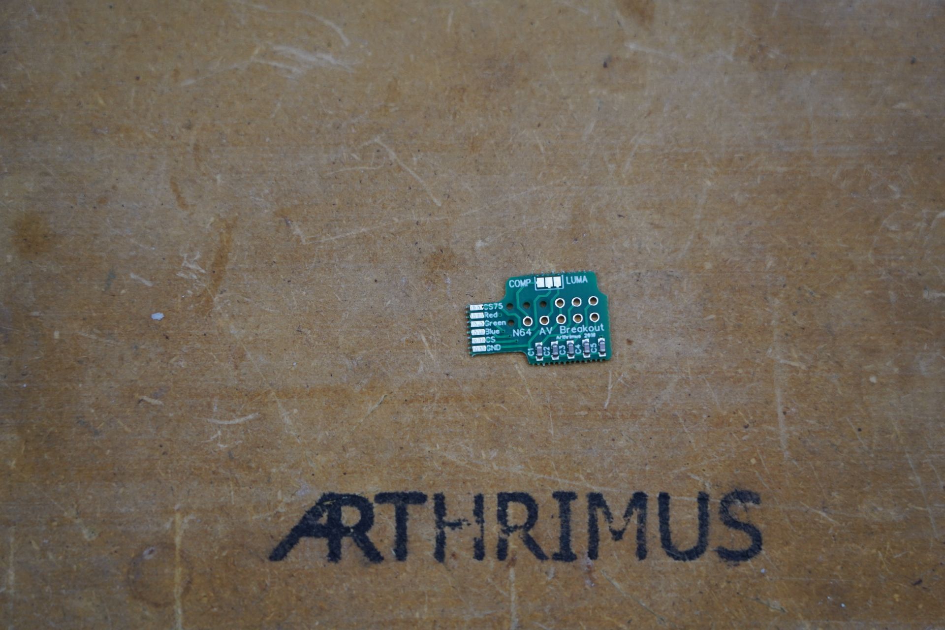
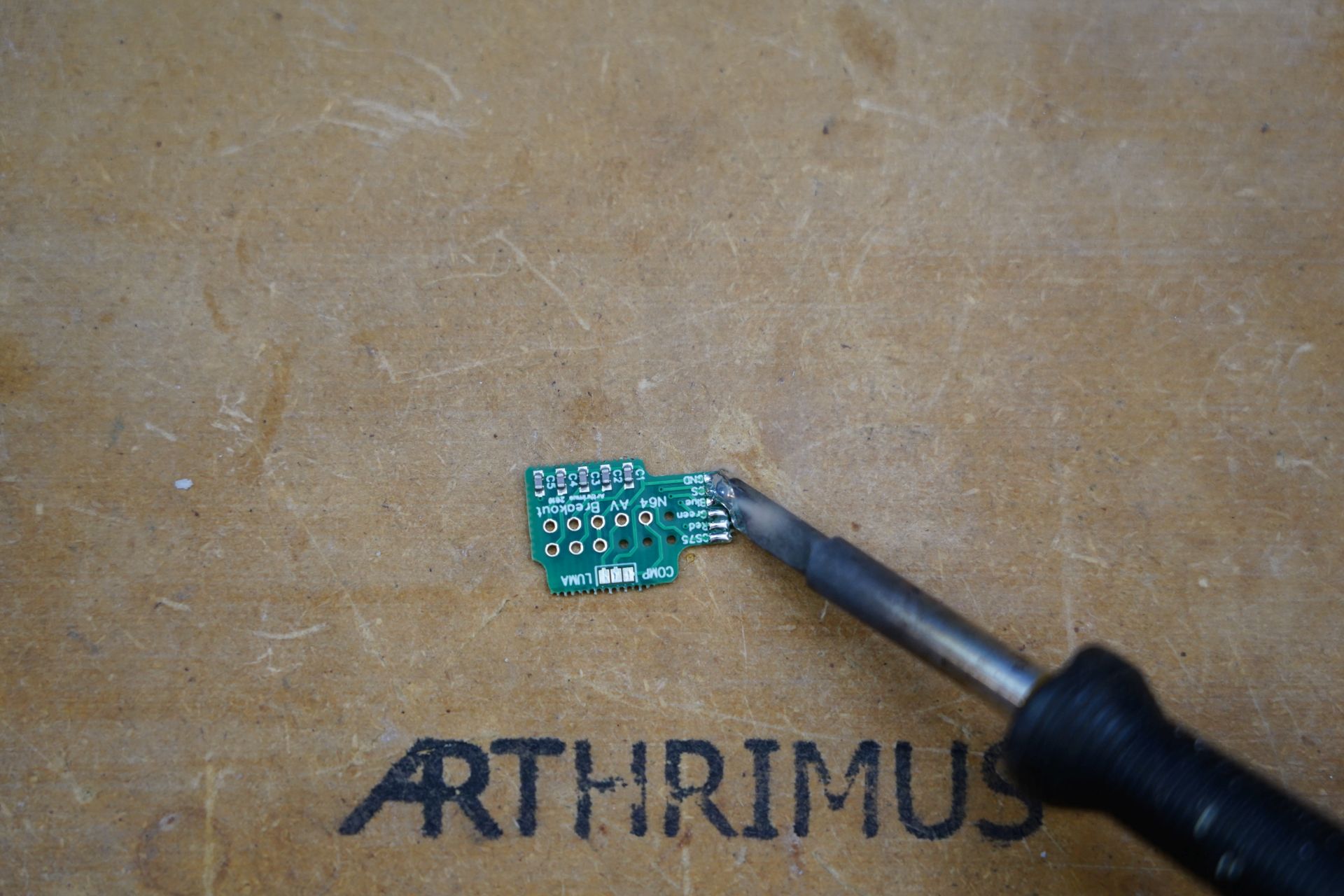
Then solder the other end of the analog wire to the N64 AV Breakout board. Make sure that the wires are oriented so that they are soldered to the same pads on both the N64 AV Breakout Board and the N64RGBv1 Board. Example CS75 on the N64RGBv1 should be connected to CS75 on the N64 AV Breakout board, etc.
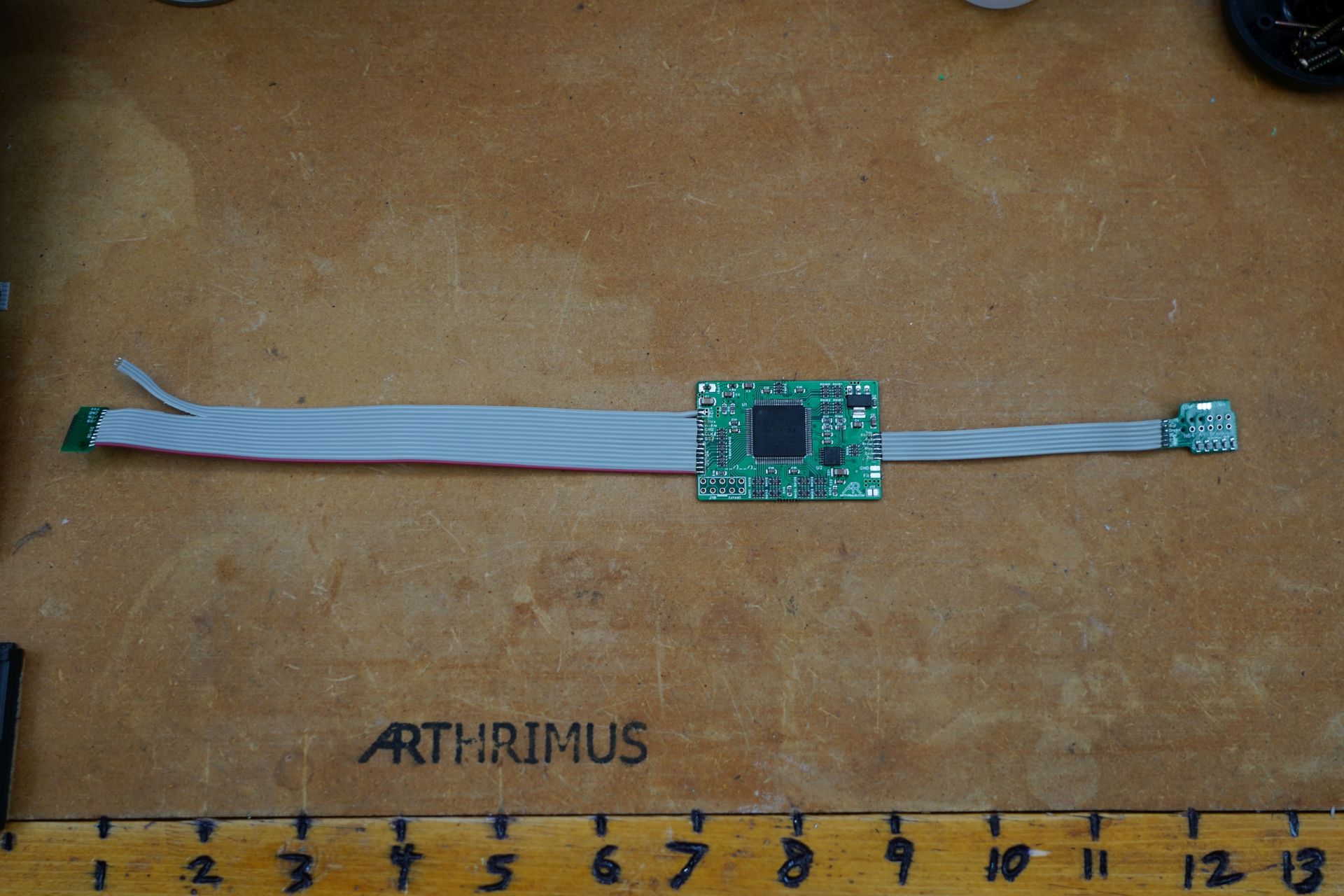
This is what the fully prepped mod board should look like.
Step 4:
Now we will begin installing the mod on the N64 motherboard.
First align the MAV-NUS adapter so that the pad on the side with the red stripe lines up with pin 1 of the MAV-NUS chip.
Tack the MAV-NUS adapter in place with a small amount of solder
Then add flux and solder the rest of the pins of the MAV-NUS adapter, making sure to cleat any bridges on any of the pins.
The final result should look like this.
Step 5:
Gently fold the ribbon cable over the top of the MAV-NUS chip, then fold it again up towards the AV port. The remaining 3 wires that were not soldered to the MAV NUS adapter should be facing towards the controller ports.
Separate the 3 wires from one another.
Further separate the outside wire from the other two and pull it back until it is closer to the 5V regulator marked U13.
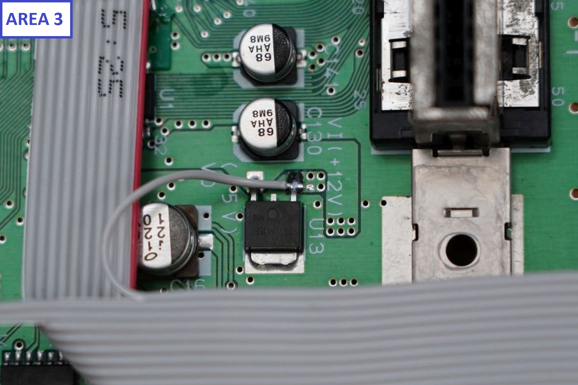
Add some extra solder to the top pad of U13 that is labeled +12v
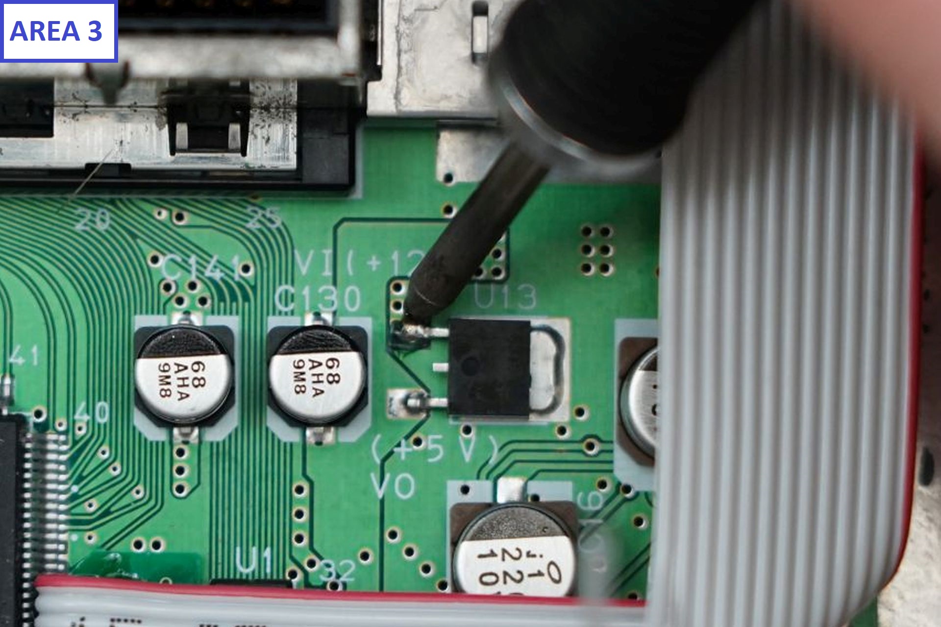
Then solder the outside wire of the ribbon cable to the pad that you tinned.
Step 6:
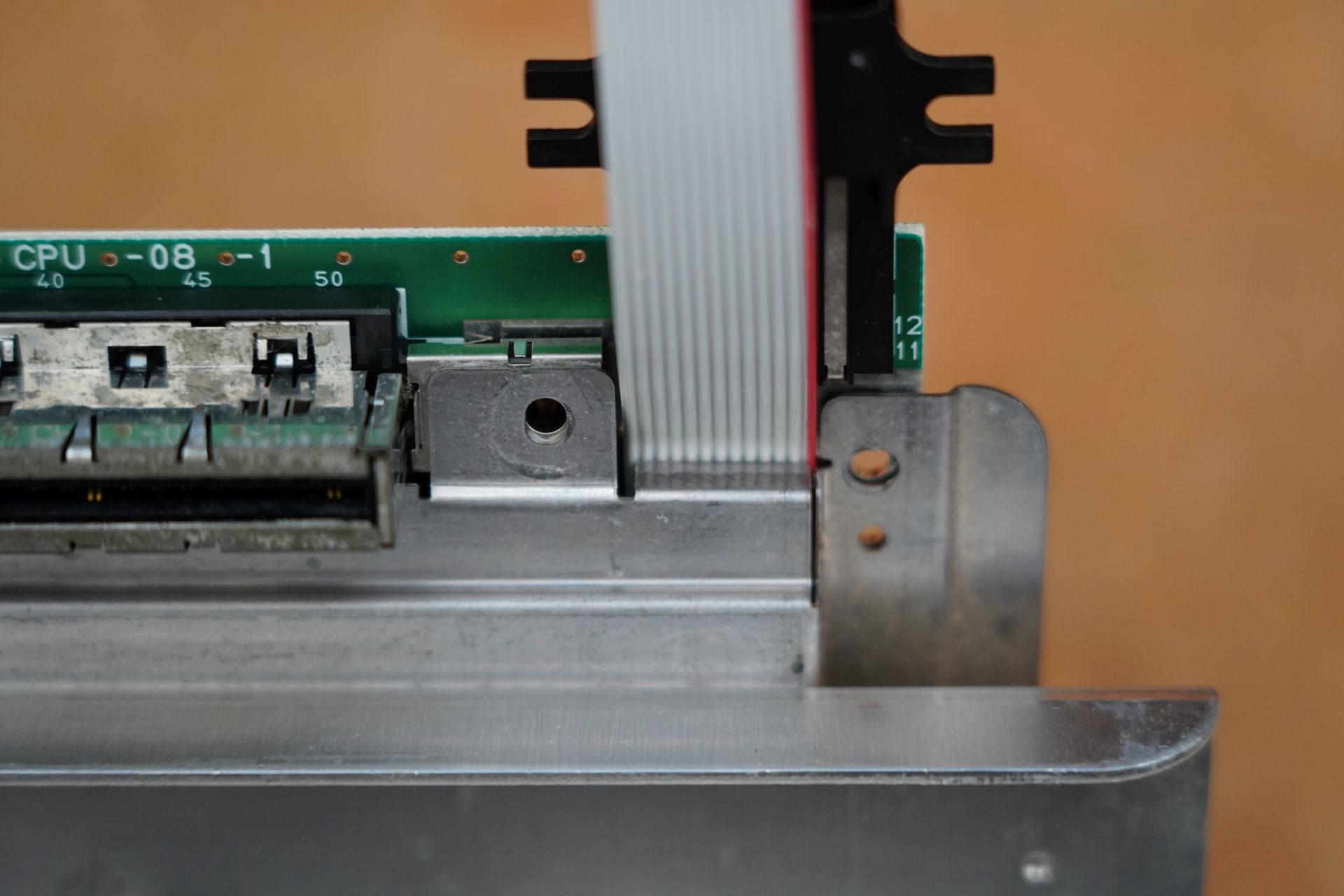
The two remaining wires from the ribbon cable should be CTRL on the left, and RST on the right. Those wires will connect to the following locations.
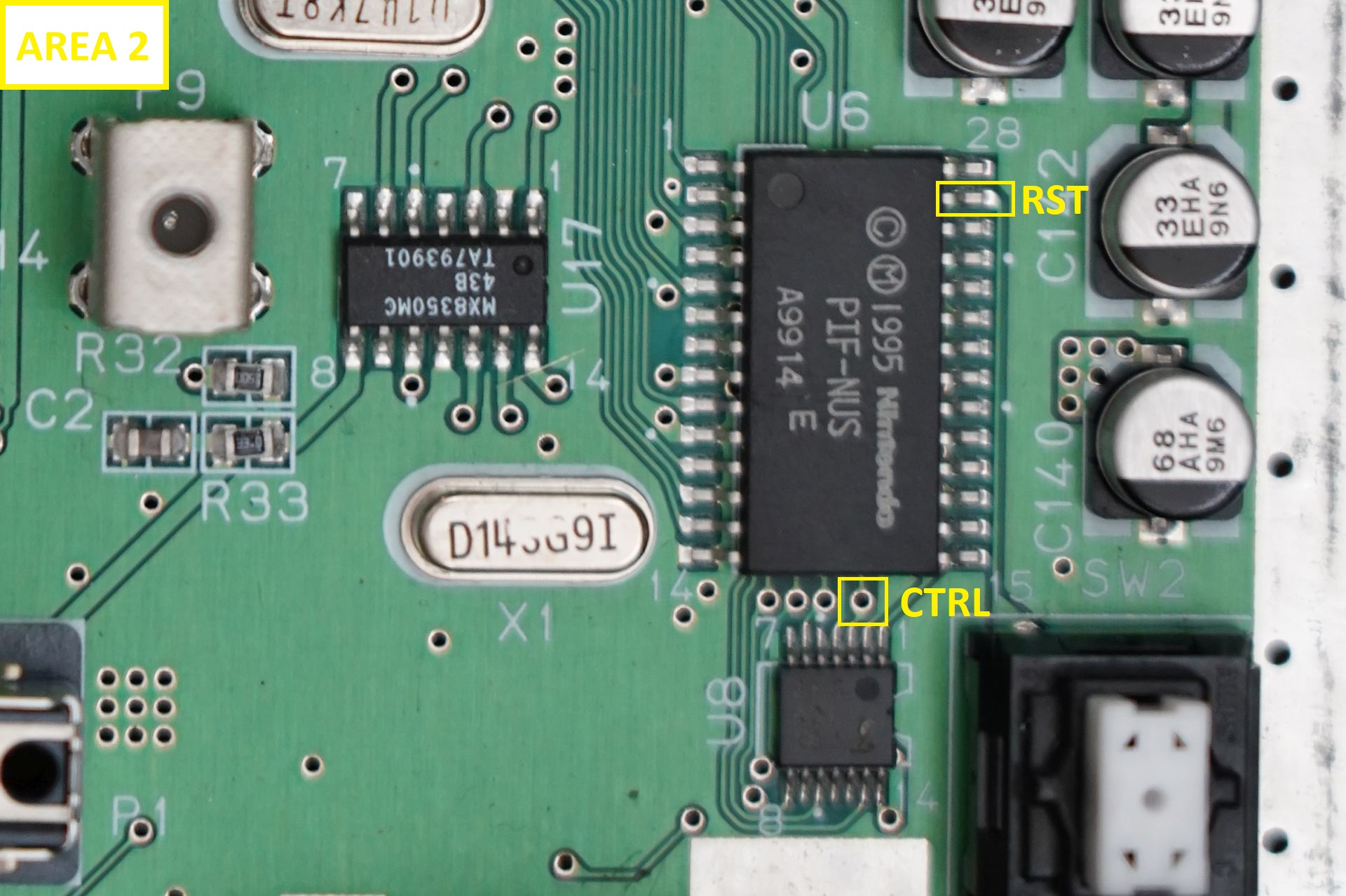
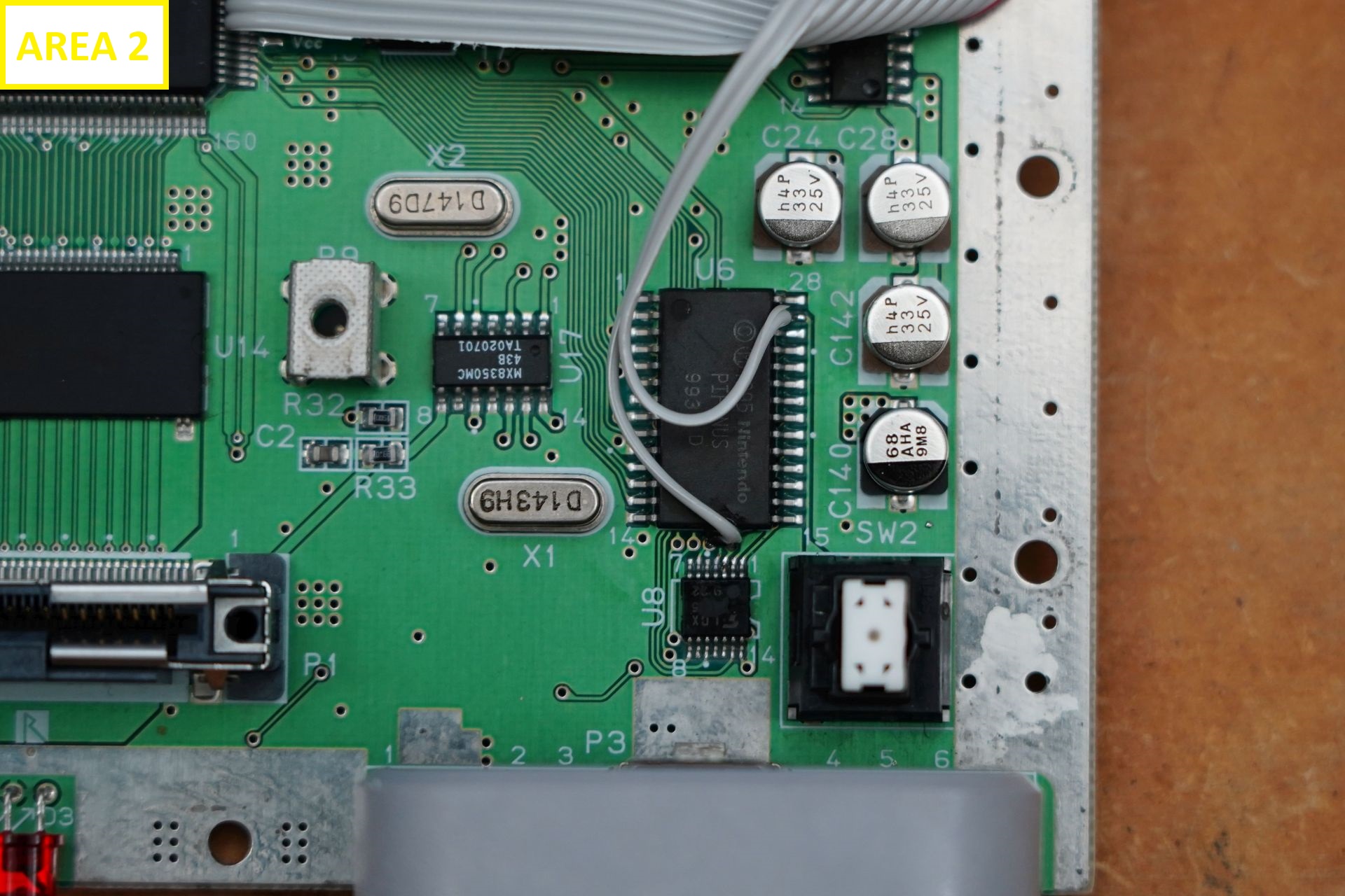
For the CTRL wire, you need to insert the wire into the rightmost of the 4 vias below the PIF-NUS chip.
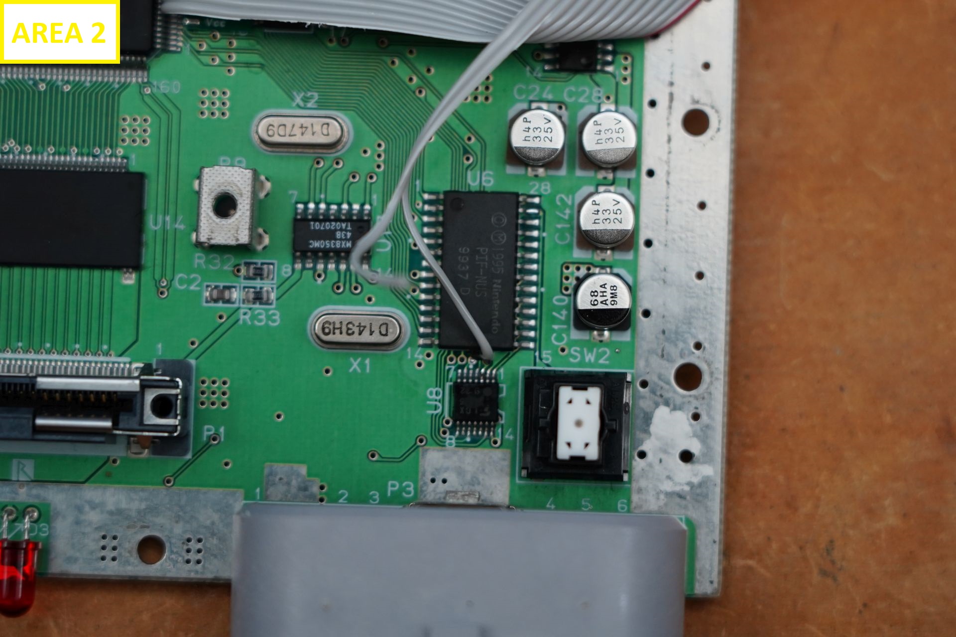
You then need to solder the wire into the via.
Next the remaining wire needs to be connected to pin 27 of the PIF-NUS as shown below.
Step 7:
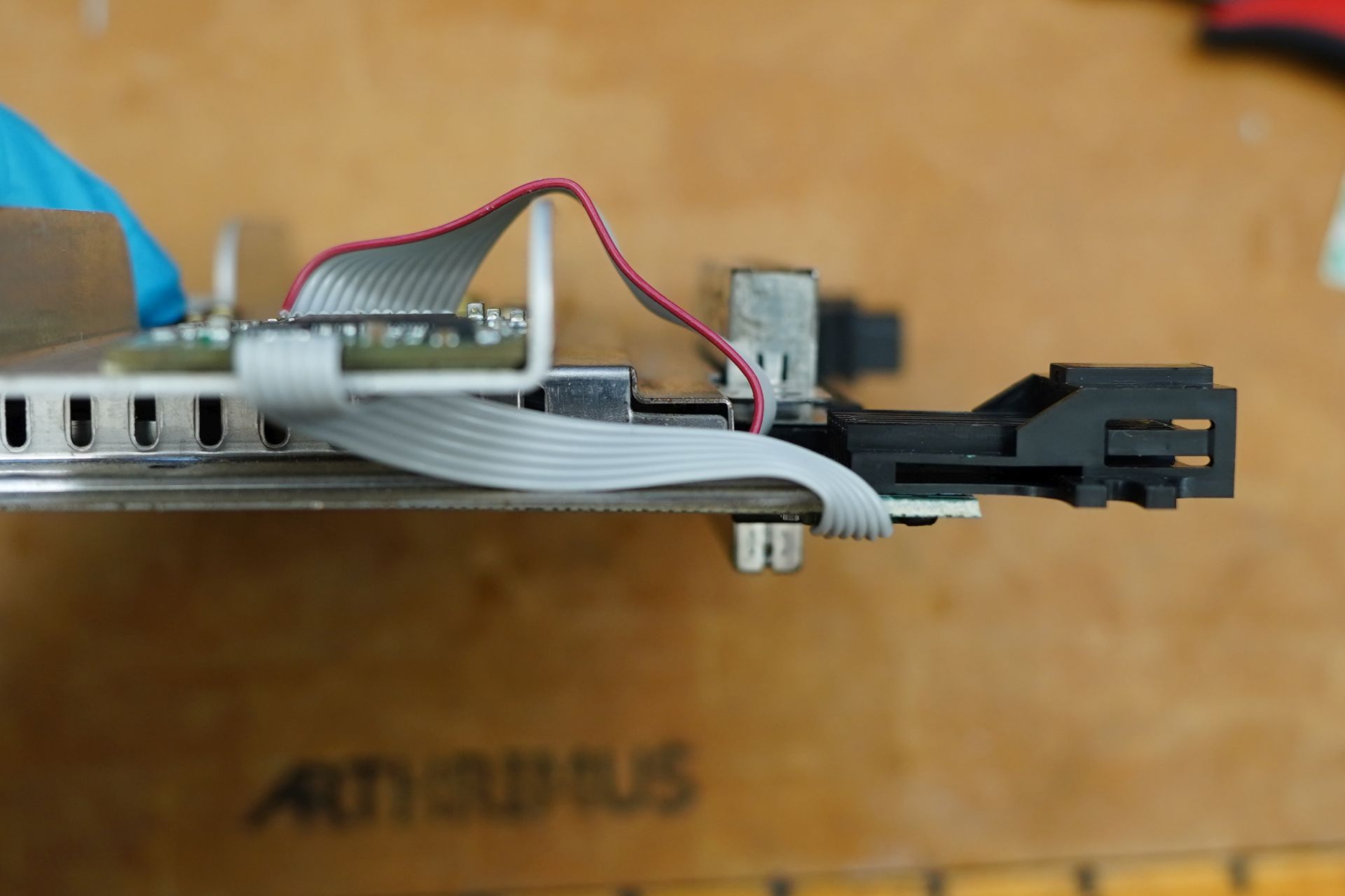
pass the ribbon cable to the right of the cartridge slot and over the top of the AV port, and place the shielding back onto the motherboard making sure that the ribbon cable is not being pinched or cut by the shielding.
Then on the bottom of the N64RGBv1 add the provided double sided tape.
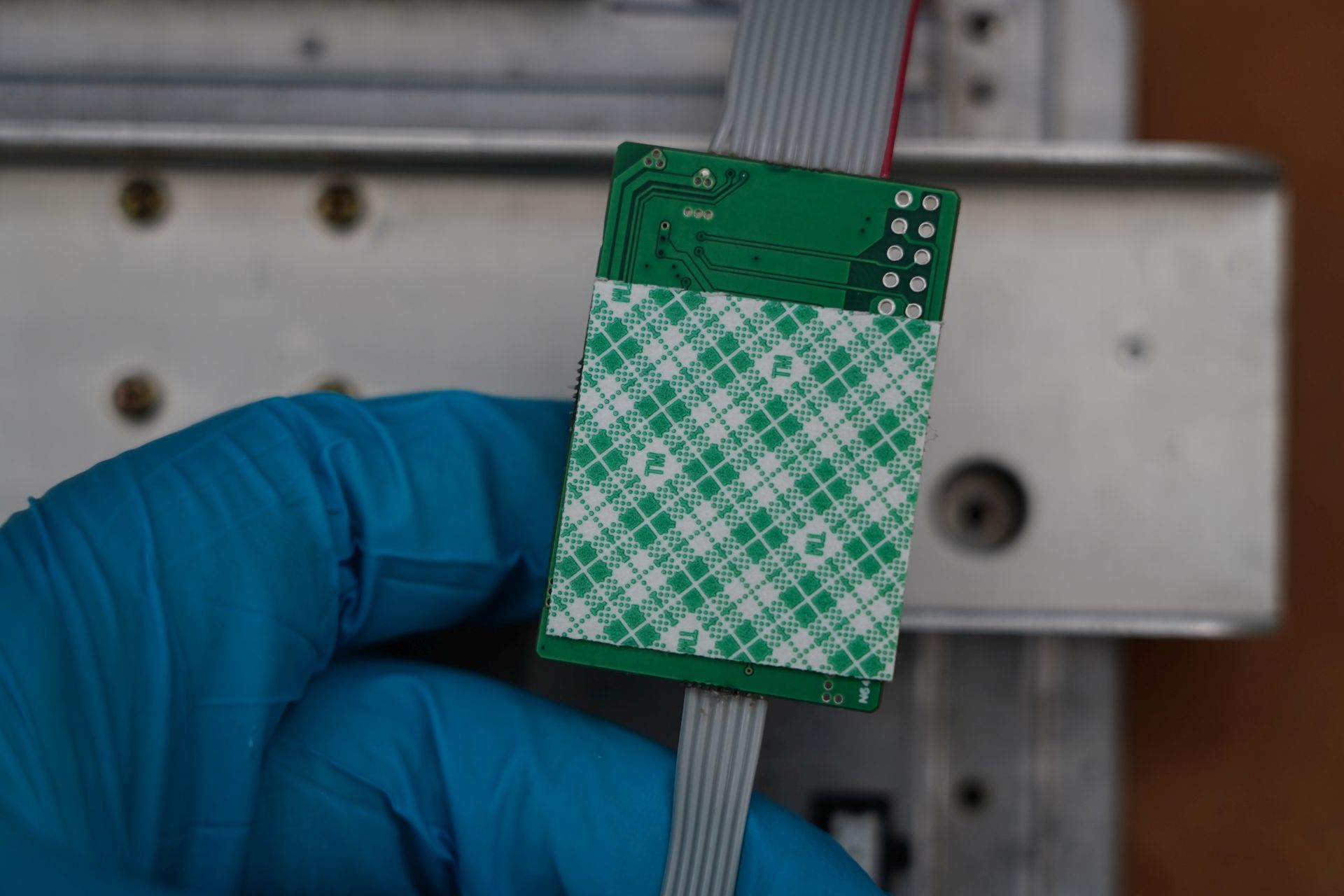
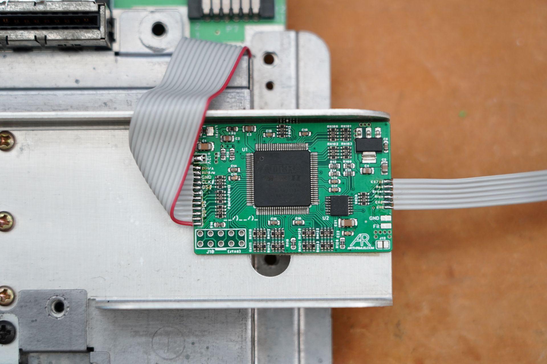
Peel the double sided tape and stick it in place on the top heatsink as shown below. Make sure that the ribbon cable has some slack and is not pulling on the pads of the N64RGBv1 board. The provided ribbon is exactly the correct length so if it is too tight, make sure that the ribbon cable is not pinched somewhere underneath the shielding.
Step 8:
Flip the motherboard over and place the N64 AV Breakout board onto the pins of the AV port as shown below.
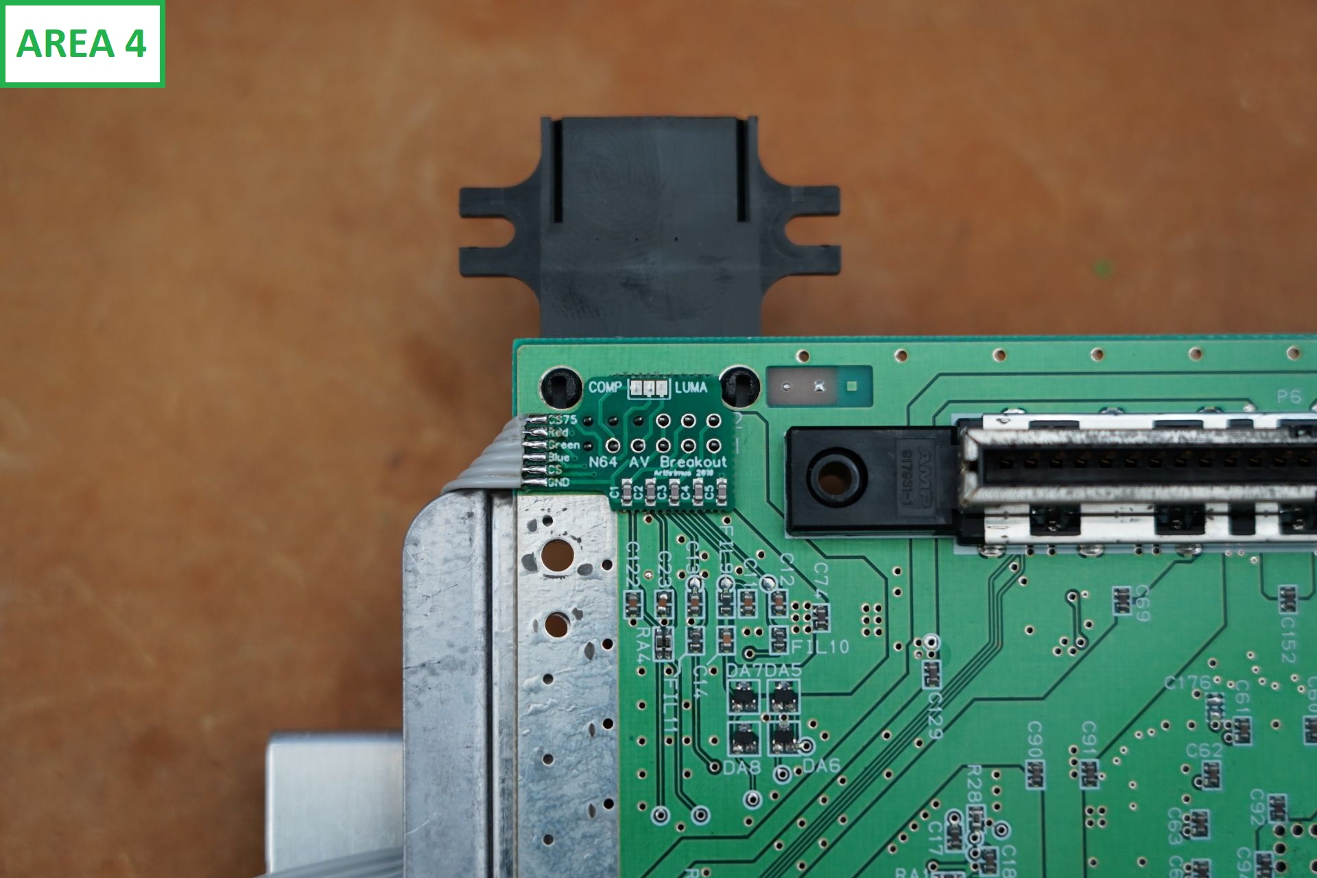
Solder the pins in place
Fold the cable from the N64 AV Breakout as shown below.
Step 9:
Reassemble your N64 and enjoy RGB video!