The Vewlix Console I/O V4 is an enhanced drop in I/O for the Vewlix control panel that allows you to easily connect 2 Brook fighting boards, or other compatible controller PCBs to your Vewlix controls without any custom wiring or modifications needed. It features full button remapping of up to 8 buttons, Home/Select/Touchpad/L3/R3 button emulation via button combos, user remappable coin switch functionality, optional coin counter iteration, and an integrated 5v 3Amp power regulator. The following instructions explain how to use each of these features.
Button Remapping and Autofire.
To enter button remapping mode hold any 2 face buttons and START simultaneously for 3 seconds. Once in remapping mode press each button the corresponding number of times to achieve the desired output based on the list below.
- Button 1 = 1 press
- Button 2 = 2 presses
- Button 3 = 3 presses
- Button 4 = 4 presses
- Button 5 = 5 presses
- Button 6 = 6 presses
- Button 7 = 7 presses
- Button 8 = 8 presses
- N/A = 9 presses
Press Start to exit remapping mode.
To enter auto fire programming mode hold any 1 face button and START simultaneously for 3 seconds. Once in auto fire programming mode press each button that you want to set as auto fire the number of times that corresponds to the desired speed in the list below.
- ~30hz = 1 press
- ~20hz = 2 presses
- ~15hz = 3 presses
- ~12hz = 4 presses
- ~7.5hz = 5 presses
- ~6hz = 6 presses
Press Start to exit auto fire mode.
Profile selection:
The Vewlix Console I/O V4 supports 6 independent Button Remapping and Auto Fire profiles per player. In order to select a profile you must hold one of the following button combinations for 3 seconds.
- Profile #1 = Start + B1 + B2 + B3
- Profile #2 = Start + B2 + B3 + B4
- Profile #3 = Start + B3 + B4 + B5
- Profile #4 = Start + B4 + B5 + B6
- Profile #5 = Start + B5 + B6 + B1
- Profile #6 = Start + B6 + B1 + B2
Button Combos for Select/Home/Touchpad button emulation:
- Select = B1 + B2 + Start
- Home = B2 + B3 + Start
- Touchpad Button = B1 + B2 + B3 + Start
- L3 = B4 +B5 + Start
- R3 = B5 + B6 + Start
Coin Mechanism Button Mapping:
You can map the coin mechanism to trigger a button press by pressing and holding the Service Switch for 3 seconds. This will cycle through each of the available options and the Player 1 and Player 2 status LEDs will blink the number of times that corresponds to the current setting.
- 1 Blink = P1 Select
- 2 Blinks = P1 Home
- 3 Blinks = P1 Touchpad
- 4 Blinks = P1 L3
- 5 Blinks = P1 R3
- 6 Blinks = P1 Start
Other Functions:
- Coin Counter control. The PCB is wired so that the coin counter will properly iterate any time the coin mechanism is triggered. You can toggle this feature on or off by pressing an holding the Service and Test Switches simultaneously for 3 seconds. When Coin Counter mode is off the Player 1 and 2 Status LEDs will flash rapidly once. When Coin Counter mode is enabled the Player 1 and 2 Status LEDs will flash rapidly twice.
-
- Home/Select/Touchpad/L3/R3 emulation enable/disable. You can toggle the button emulation function on or off by pressing and holding the Test Switch for 3 seconds. The Player 1 and 2 Status LEDs will blink slowly each time you toggle this mode.
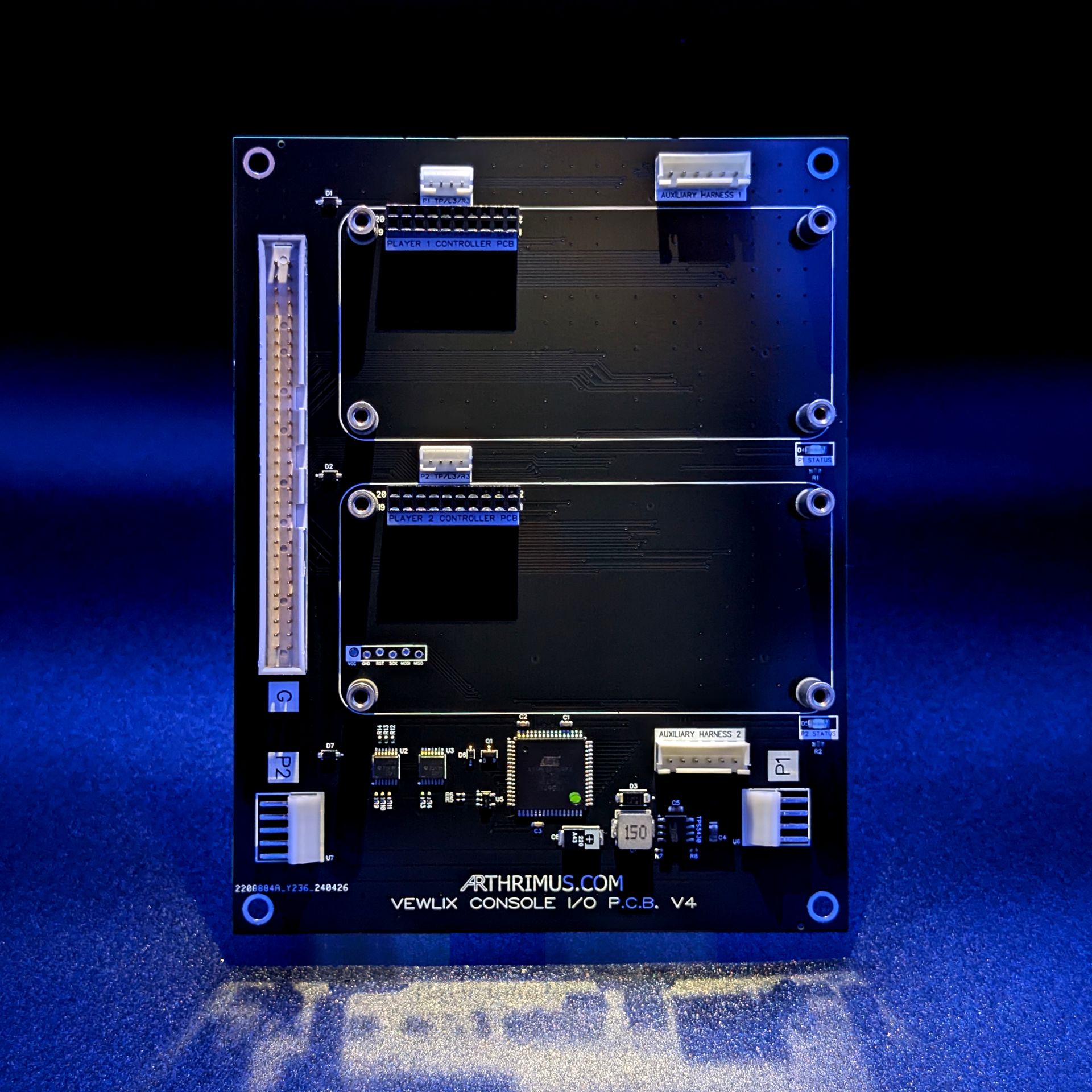
Connectors Description:
- “Player 1 and 2 Controller PCB” headers. These are 2×10 2.54mm pin headers that are mapped to the standard Brook fighting board pinout. You can use any controller PCB that uses the Brook standard 20 pin header for controls.
-
- “P1 and P2 TP/L3/R3” These are JST PH2.0 headers that are mapped to the standard Brook TP/L3/R3 header pinout used on all Brook fighting boards. You can use the included cables to connect any PCB that uses the Brook pinout for the Touchpad/L3/R3 buttons.
-
- “G” Harness connector. This is the Standard Vewlix 60 pin G harness connector for the control panel harness. This is what connects the buttons from your Vewlix to the Console I/O.
-
- “P1” Harness connector. This connects to the P1 harness in your Vewlix to supply 12v to the power regulator onboard the Vewlix Console I/O V4. This must be connected for the Console I/O V4 to function properly.
-
- “P2” Harness connector. This is the power output from the Vewlix Console I/O. It supplies 5v, 12v and GND.
-
- Auxiliary Harness 1: Extra button harness that allows you to connect dedicated buttons for Player 1 and 2 Home and Select.
-
- Auxiliary Harness 2: Extra button harness that allows you to connect dedicated button for Player 1 and 2 B7 and B8
Connector Pinouts:
‘G’ 60 Pin JST RA connector:
01 (+12V)
02 (+12V)
03 (+5V)
04 (+5V)
05 (ADC0)
06 (ADC1)
07 (ADC2)
08 (ADC3)
09 (ADC4)
10 (ADC5)
11 (ADC6)
12 (Analogue-GND)
13 (Analogue+5V)
14 (Analogue-GND)
15 (Coin SW1)
16 (Coin SW2)
17 (1P Service)
18 (2P Service)
19 (1P Start)
20 (2P Start)
21 (Test Sw)
22 (Tilt Sw)
23 (1P Up)
24 (2P Up)
25 (1P Down)
26 (2P Down)
27 (1P Left)
28 (2P Left)
29 (1P Right)
30 (2P Right)
31 (1P SW1)
32 (2P SW1)
33 (1P SW2)
34 (2P SW2)
35 (1P SW3)
36 (2P SW3)
37 (1P SW4)
38 (2P SW4)
39 (1P SW5)
40 (2P SW5)
41 (1P SW6)
42 (2P SW6)
43 (1P SW7)
44 (2P SW7)
45 (1P SW8)
46 (2P SW8)
47 (Coin Meter 1)
48 (Coin Meter 2)
49 (1P-Output 1)
50 (2P-Output 1)
51 (1P-Output 2)
52 (2P-Output 2)
53 (1P-Output 3)
54 (2P-Output 3)
55 (1P-Output 4)
56 (2P-Output 4)
57 (GND)
58 (GND)
59 (GND)
60 (GND)
‘P1’ 4pin JST NH Power in
01 (+12V)
02 (+12V)
03 (GND)
04 (GND)
‘P2’ 5pin JST NH Power out
01 (+12V)
02 (+5V)
03 (+5V)
04 (GND)
05 (GND)
‘Auxiliary Harness 1’ 6pin JST XH
01 (P1 Select)
02 (P1 Home)
03 (GND)
04 (GND)
05 (P2 Select)
06 (P2 Home)
‘Auxiliary Harness 2’ 6pin JST XH
01 (P1 B7)
02 (P1 B8)
03 (GND)
04 (GND)
05 (P2 B7)
06 (P2 B8)